31
H U I R E F E R E N C E G U I D E
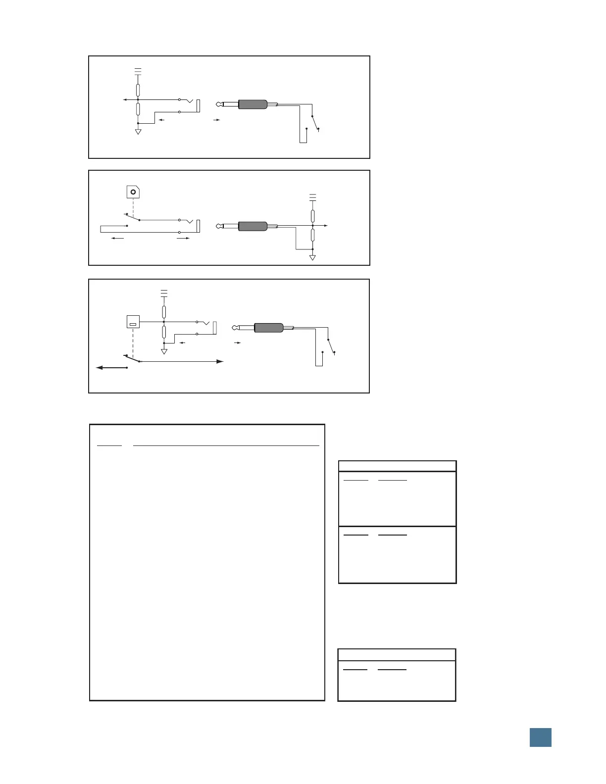
Footswitch
Normally Open (N.O.)
Talkback
+5V
Remote
Talkbk
Trigger
Talkback
Bus
Max Current: 5mA
FOOTSWITCH IN Block Diagram
Relay Out
Relay Out
1 and 2
+5V
Logic
Active Low
Max Current: 100mA
+5V
Logic
Active Low
Footswitch In
1 and 2
Footswitch
Normally Open (N.O.)
Max Current: 5mA
RELAY OUT Block Diagram
REMOTE TALKBACK TRIGGER Block Diagram
F-Key Function performed
F1 Clears clip and peak holds from the meter.
F2 Activates/deactivates Relay Outputs 1 and 2.
(When activated, Relay Output 1 is controlled
by the PLAY button in the Transport Section.
Relay Output 2 is controlled by the RECORD
button.)
F3 Enables/disables the audible click function for
the V-Pots below the VFD. This function
applies only while in Assign mode.
F4 Displays the version number of the HUI pers-
onality file currently installed in the host computer.
F5 Reserved for future expansion.
OPT+F5 Enables/disables the audible click function for
the buttons.
F6 Reserved for future expansion.
F7 Reserved for future expansion.
F8/ESC Serves as an escape switch to cancel any
assignment mode or onscreen dialog.
RS-232 9-Pin D-Sub Connector
Pin No. Function
Pin 2 TXD
Pin 3 RXD
Pin 5 Ground
RS-422 9-Pin D-Sub Connector
Pin No. Function
Pin 2 TX–
Pin 3 RX+
Pin 4 Ground
Pin 7 TX+
Pin 8 RX–
Serial Port
Serial Port Pin-Out Chart
RS-232 9-Pin D-Sub Connector
Pin No. Function
Pin 2 TXD
Pin 3 RXD
Pin 5 Ground
Expansion Port
Expansion Port Pin-Out Chart
SPECIFICATIONS
Function Key Table