19
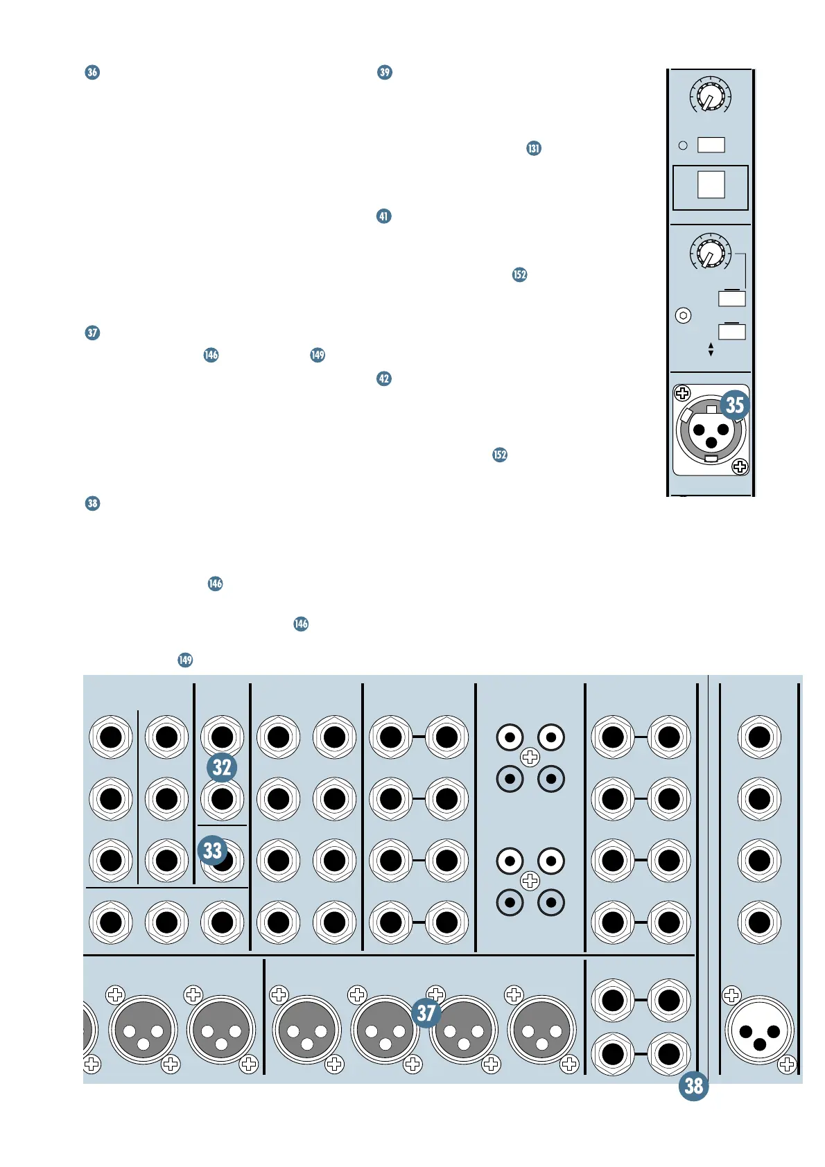
INTERCOM
Point Before: Externally supplied Clear-
Com
™
or compatible party-line intercom
line, with power.
Point After: SR40•8 intercom interface,
headphone amplifiers, and talkback system.
This connector accepts a 3-pin male XLR
connector connected to a Clear-Com or com-
patible party-line intercom system. This system
uses the following wiring: pin 1 = ground/0V,
Pin 3 = audio + DC signalling, pin 2 = 28–30VDC.
The ground pin of this connector is isolated
from the SR40•8’s ground system.
MATRIX OUTPUTS
Point Before:
MATRIX
,
MASTER
level .
Point After: Balanced or unbalanced cable
with female XLR connector (pin 2 = hot, pin 3
= cold, pin 1 = shield).
If necessary, patch these outputs to the ampli-
fier inputs of additional speaker systems or use
for other applications requiring composite mixes.
MATRIX INPUTS
Point Before: Balanced or unbalanced line-
level cable with
1
⁄
4
" TRS or TS connector, (tip
= hot, ring = cold, sleeve = shield).
Point After:
MATRIX
.
Signals injected into these jacks are fed
directly to their respective
MATRIX
out-
puts, governed only by the
MATRIX
section’s
MASTER
levels .
DC POWER IN
Arguably the most important connector on
any console, the SR40•8 will not work until
you’ve connected its power cable here.
POWER SUPPLY STATUS
LEDs in the out-
put section will confirm that the console is
fully powered.
MIDI IN/OUT
This is where you interface the SR40•8 with
an external sequencer or other MIDI device, to
enable
ULTRA MUTE
™
to perform complex
automated muting moves. Connect the MIDI
OUT of the sequencer to the
MIDI IN
of the
SR40•8, and the
MIDI OUT
of the SR40•8 to
the MIDI IN of the sequencer.
DATA
This connector allows you to connect the
SR40•8 with an external computer via an
RS-232 connector, to enable remote control of
the
ULTRA MUTE
™
system. If your
application requires RS-422, use an external
protocol adapter.
MAIN INSERTS
(BAL/UNBAL)
HEADPHONES
R
L
LEFT RETURN
2
1
4
3
6
5
8
7
R
R
R
R
L
L
L
L
RIGHT SEND
LEFT SEND
MONITOR
(BAL/UNBAL)
AUX SEND
(BAL/UNBAL)
"B" AUX RETURNS
(BAL/UNBAL)
1
2
3
4
(MONO)
(MONO)
(MONO)
(MONO)
R
R
R
R
L
L
L
L
A1
A2
A3
A4
(MONO)
C
A
D
B
(MONO)
(MONO)
SOURCE =
MASTER L-R
SOURCE =
MATRIX C&D
(MONO)
MATRIX DMATRIX CMATRIX BMATRIX A
CENTER
RIGHT
INSERT RETURN
MIC 24
INSERT SEND
24
DIRECT OUT
LINE IN
TAPE
TAPE
R
L
R
L
R
L
R
L
INPUT OUTPUT
TAPE TAPE
INPUT OUTPUT
TAPE A
TAPE B
TALKBACK
MATRIX OUTPUTS MATRIX INPUTSMAIN OUTPUTS
CNTR SEND
RIGHT RETURN
CNTR RETURN
L-INSERT R-INSERT
TAPE
MAIN AUX RETURNS
OO
MAX
OO
MAX
TALKBACK MIC
LEVEL
ON
IGNORE
CALL
COMMUNICATIONS
OSCILLATOR
RECEIVE
400Hz
PINK NOISE





 To Next Page