37
MAXLOW
MAXLOW
INPUT
SECTION
OUTPUT
SECTION
PFL
AFL
PFL
AFL
METER
V.+
POWER SUPPLY
STATUS
V.- 5 V 12 V 48 V
DIMMER METERING
LAMP
U
OO
+15
U
OO
+15
U
OO
+15
LINE OUT
LEVELLEVEL
MUTE
INPUTS
MONITOR SOLOTAPE BTAPE A
TAPE RETURNS
PFL
AFL
PFL
AFL
MUTE
SOLO
MUTE
SOLO
RUDE
SOLO LIGHT
OUTPUTS
MONITOR
MONITOR
signals are a line-level equivalent
of the
HEADPHONES
output. The TRS
MONITOR
outputs are designed for special
situations such as these:
You can use these jacks to deliver the FOH
(front-of-house) headphone mix to an engineer
operating a secondary stage monitor console.
If you want to drive several pairs of head-
phones via an outboard amplifier, patch these
outputs to that amp.
If the console is in a soundproof room, as in
live sound-studio work or studio recording/
mixdown, patch the
MONITOR
outputs to
your control room amplifier and speakers.
LINE OUT (LEVEL)
Point Before:
INSERT
(
HEADPHONES
) .
Point After:
MONITOR
outputs.
Just like the
HEADPHONES
, the
MONI-
TOR
outputs always receive the
LEFT/RIGHT
mix, with the
CENTER
mix blended into each
side. This control sets the level for those sig-
nals, and it follows the
PHONES
level control,
meaning that the level at these outputs is con-
trolled twice — by the
PHONES
level and by
the
LINE OUT
control.
SOLO
signals to the
MONITOR
outputs are
controlled by
SOLO LEVEL
and this
MONITOR
LINE OUT
level — the
PHONES
level has no
effect on
SOLO
signals. This is so you can
tailor the “mix level” (non-
SOLO
signals) and
the
SOLO LEVEL
independently.
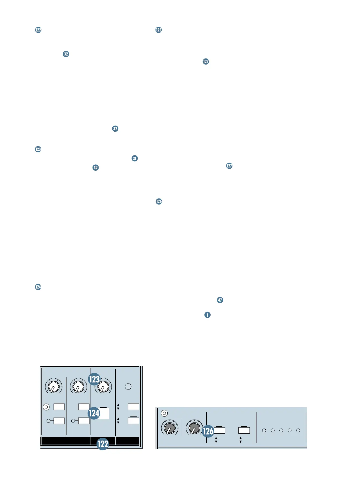
MUTE
This switch is your garden-variety DPDT
(double-pole, double-throw) switch. Engage it
and the line-level
MONITOR
outputs become
silent. The
MONITOR MUTE
is not a member
of the
ULTRA MUTE
™
system and therefore
cannot be remotely controlled.
LEFT/RIGHT/CENTER METERS
These individual Meters give you constant
visual information about the signal level in
that mix. With the
METERING: OUTPUT
SECTION PFL/AFL
switch set to
PFL
(up),
the Meters display the pre-Fader signal of the
mix. With the switch down, the Meters display
the post-Fader output of the mix.
These three Meters, unlike the other fifty-
six, have a secondary purpose — to display
SOLO
levels. Whenever
SOLO
is engaged, all
three Meters’ inputs change from the
LEFT/
CENTER/RIGHT
mix signals to the
SOLO
sig-
nals. The
PFL SOLO
signal will appear on the
CENTER
Meter and the
AFL
signals appear on
the
LEFT/RIGHT
Meters.
A 0dB reading on the Meters represents a
0dBu output signal, when the
METERING:
OUTPUT SECTION PFL/AFL
switch is
engaged (
AFL
). In other words, 0VU=0dBu.
METERING
INPUT SECTION PFL/AFL
This switch determines the Meter’s source
signal for the Channels and the
MAIN AUX
RETURN
(
A1
–
A4
). With the switch up, in
PFL
mode (Pre-Fader Listen), signals are
sent to the Meters pre-Fader, pre-
MUTE
, and
pre-
PAN
. In fact, in
PFL
mode, these Meters
may save you the time of having to use
SOLO
,
if all you need is a signal confirmation. With
the switch down, in
AFL
mode, signals will be
sent to the Meters post-Fader, representing
the output of the circuit.
With this switch set to
PFL
, you can
perform on-the-fly
TRIM
settings, as
explained in the Turbo Method of the Level-
Setting Procedure
.