Page 19 of 31
TROUBLESHOOTING GUIDE
Problem Cause Remedy
Fluid will not flow
through meter
a) Foreign matter blocking rotors
b) Line strainer blocked
c) Damaged rotors
d) Meter connections over tightened
e) Fluid is too viscous
a) Dismantle meter, clean rotors (strainer must be fitted in line)
b) Clean strainer
c) Replace rotors (Strainer must be fitted in line)
d) Re-adjust connections
e) See specifications for maximum viscosity
Reduced flow
through meter
a) Strainer is partially blocked
b) Fluid is too viscous
a) Clean strainer
b) See specifications for maximum viscosity
Meter reading
inaccurate
a) Fluid flow rate is too high or too low
b) Air in fluid
c) Excess wear caused by incorrect
installation
a) See specifications for minimum and maximum flow rates
b) Bleed air from system
c) Check meter body and rotors. Replace as required. Refer to
installation instructions
Meter not giving a
pulse signal
a) Faulty hall effect switch
b) Faulty reed switch
c) Magnets failed
a) Replace PCB Board
b) Replace PCB Board
c) Replace magnets
LCD register not
working
a) Battery not connected properly
b) Battery flat
c) Faulty wiring connections
d) Faulty LC Display
e) Faulty connection from LC Display
a) Check battery connections
b) Replace battery
c) Check wiring for loose or faulty connections
d) Replace LC Display
e) Check wiring connections
Macnaught provides an comprehensive set of „Maintenance Videos‟ to assist the end user in
all aspects of service and / or repair of the flow meter range.
This web based resource can be accessed by scanning the QR.
MAINTAINENCE VIDEOS
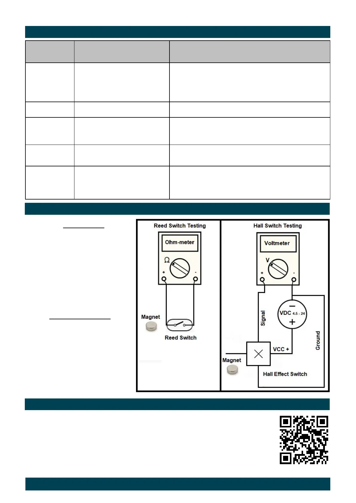
TESTING REED / HALL SWITCHES
Testing of Reed Switch requires
Neodymium magnet (at least 220
Gauss) and Macnaught display/PLC/
FMS/Ohmmeter/Multimeter. If changes
in reading are seen by waiving magnet
near the reed switch, means it is
working fine. Otherwise, the reed switch
is faulty.
Testing Hall Effect Switch requires
Neodymium magnet (at least 220
Gauss), Power Supply/Battery (4.5 - 24
V DC) and Multimeter/Voltmeter.
Correct wiring is shown in the picture.
Check if only one of the magnet poles
changes the signal reading on the volt-
meter. It is a clear indication that the
switch is working perfectively. If hall
switch signal is not changing then Hall
switch is faulty.