Page 3 of 31
IMPORTANT INFORMATION (READ CAREFULLY)
FLUID COMPATIBILITY: Before use, confirm the fluid (liquid) to be used is compatible with the meter. Refer to
industry fluid compatibility charts or consult your local representative or distributor for advice.
STRAINER: To prevent damage from dirt or foreign matter, it is recommended that a Y type or Basket type mesh
strainer be installed as close as possible to the inlet side of the meter.
Meter 1/4” 74 micron / 200 mesh
Meter 1/2”- 2” 250 micron / 60 mesh
Meter 3”- 4” 420 micron / 40 mesh
When a strainer is installed it should be regularly inspected and cleaned. Failure to keep the strainer
clean will dramatically effect flow meter performance. Contact your local representative for advice.
AIR PURGE / LINE PRESSURE: To prevent damage caused by air purge, slowly fill the meter with fluid.
To reduce pressure build-up turn off the pump at the end of each day.
FLOWMETER USAGE: The flow meter shall be used exclusively with liquids. No gases permitted to flow.
Presence of gases could create severe hazard and damage
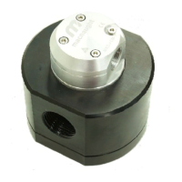
Fluid passing through the meter causes the rotors to turn, as shown below. One of the rotors (the active rotor) is
fitted with magnets.
The passing of the magnets are picked up by the electronic sensor. The excitation of this switch provides a „Raw
Pulse Output‟ which relates to the K-Factor. (e.g. KF 36 = 36 pulses per litre of fluid passed)
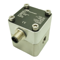
This Pulse Output Signal can either be fed to an external receiving element (e.g. Data Logger or PLC) or
alternatively to an LC Display which conditions the Pulse signal to display volume of fluid passed. (e.g. Display 1
Litre per for every 36 pulses received)
OPERATING PRINCIPLE