OPERATION
MULTI-FUNCTION DISPLAY
Operating Manual MT 25 / 30 YT 75
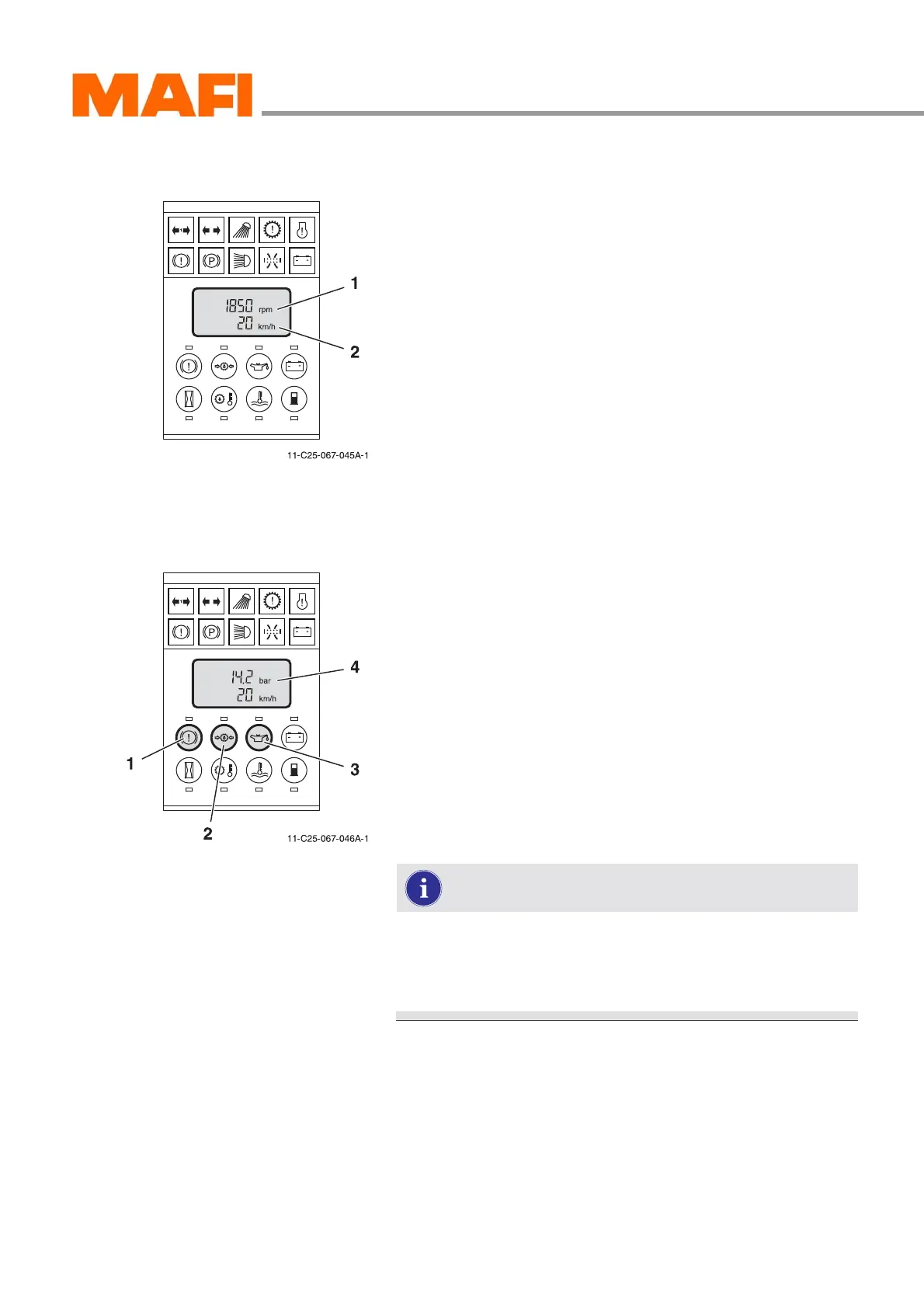
Normal display
Fig. 64: Normal display
1 Motor speed
2 Driving speed
After ignition switch-on, the multi-function display conducts
a self-test.
z All function indicators illuminate.
z All display segments are activated.
z All sensors are checked.
After the self-test, the multi-function display automatically
changes to normal display, as long as there are no sensor
error messages. The normal display shows:
z driving speed in km/h or mph,
z motor rpm speed.
Pressure indicator
Fig. 65: Pressure indicator
1 Button “Brake pressure”
2 Buttons “Transmission oil pressure”
3 Button “Motor oil pressure”
4 “Pressure” indicator
With the buttons 1, 2 and 3 you can read the pressures de-
scribed below. The value is shown in the display at position 4.
All pressures are shown in bar.
Switch 1:
z air reserve pressure circuit 1
z air reserve pressure circuit 2
z air reserve pressure circuit 3
The reserve pressures of circuits 1 to 3 can be dis-
played in connection with the switch “Reserve pres-
sure”. The circuit shown depends on the position of the
“Reserve pressure” switch.
Button 2:
z transmission oil pressure
Button 3:
z motor oil pressure