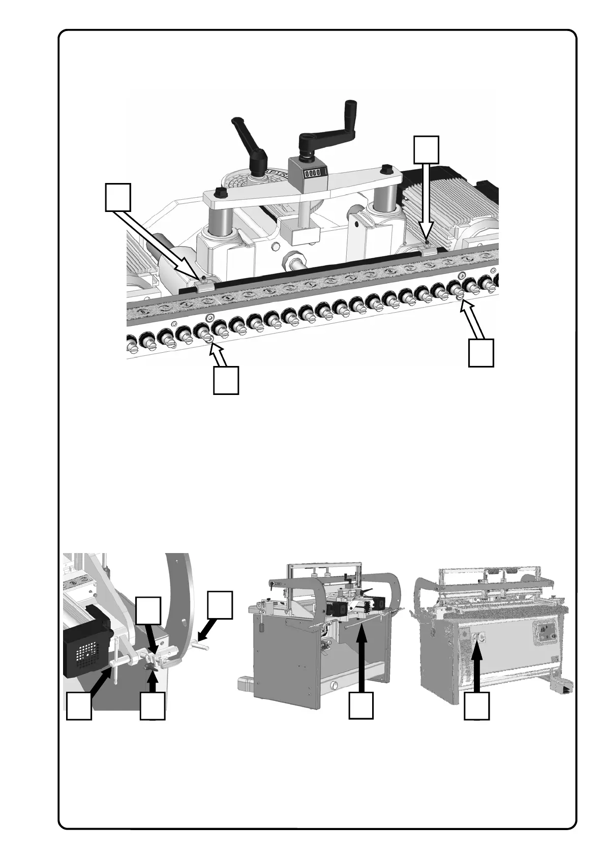
15.4 SPINDLE HEAD HORIZONTAL AND VERTICAL POSITIONING
POINT 1 “Caution danger” Carefully follow the whole procedure described below. To position the spindle head
at 90° ( POS. A ) starting from 0° as shown in the figure, proceed as follows:
− Release the handles (1 and 2)
− Use the control lever (3), positioned on the front side of the machine, and move it to the lower position.
− Lock the handles (1 and 2) again.
POINT 2 To position the spindle head at 0° starting from 90° ( POS. A ), proceed as follows:
− Check that the control lever (3), on the front side of the machine, is also positioned at 90° (lower position)
− Release the handles (1 and 2)
− Use the control lever (3) and move it to the upper position to overturn the head unit
− Lock the handles (1 and 2) again.
SPINDLE HEAD POSITIONING AT AN INTERMEDIATE ANGLE OF 45°
− Please position the head unit at 90°.
− Release the handles (1 and 2) to be able to pull out the graduated fence (4)
− Release the handle (5) and position the stop (6) at the required degrees from 0° to 90° along the gradu-
ated fence and then lock again.
− Follow the procedure described at Paragraph 15.4 Point 2 ( head positioning at 0° ) the unit will stop in
the chosen position
− Then lock the handles (1 and 2) again.
C
B
A
A
4 5
2
1 3
6
HEAD PARALLELISM ADJUSTMENT
− Partially loosen the screws ( A ) and work alternately on the screws ( B ) and nuts ( C )
− Set the drills parallel to the work table
− Firmly tighten the screws ( A )