A
B
C
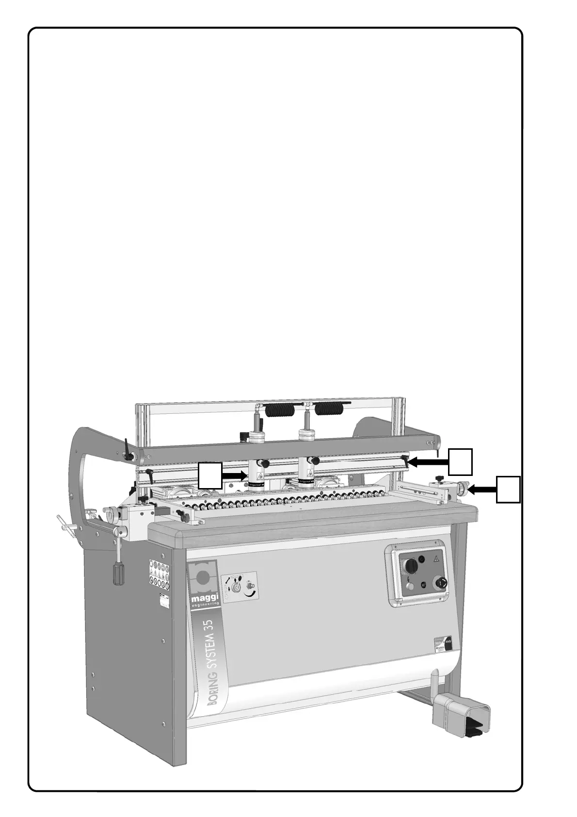
15.5 USE OF THE REFERENCE STOP FOR STANDARD 0°-90° MACHINING
STEP 1 - The side squares (A) and back stops (B) are used to position the piece to be machined in the stan-
dard working cycle.
With the spindle head at 90° and the spindle holder unit clamped in place:
−Position and lock the side squares at an appropriate distance from the drills to be used
−Position the clamp cylinder (or cylinders) (C) in the area where the piece will be worked
−Place the piece to be bored against the side squares using them as guides to position the piece under the
clamps and against the rack.
−Position the stoppers (B) above the work piece, lower the stopper reference block onto the piece and clamp
the stopper itself with the corresponding handles.
−The piece is in the right position and it is now possible to start the working cycle pressing the pneumatic
pedal to start drill feed with the engine switched on (make sure that the engine button is on). At the same
time the clamps will lock the work piece into position.
STEP 2 - W
hen the first step is over, release the pneumatic pedal to release the piece and take the bored
piece out of the machine. Release the spindle head unit, operating the overturning lever to re-position the
spindle head at 90°. Re-position the head and lock it in place, than you can start the second step:
−position the piece, that has to be joined to the one that has just been machined, against the side square un-
der the clamp (or clamps) (C) and against the back stop block.
−Once you are sure the piece has been positioned correctly, press the pedal to lock the clamp, to turn and
feed the drills.
−The piece will be released once the pedal is freed, ending the working cycle.
THE TWO PIECES THAT HAVE BEEN OBTAINED ARE NOW READY TO BE JOINED (0°-90°).