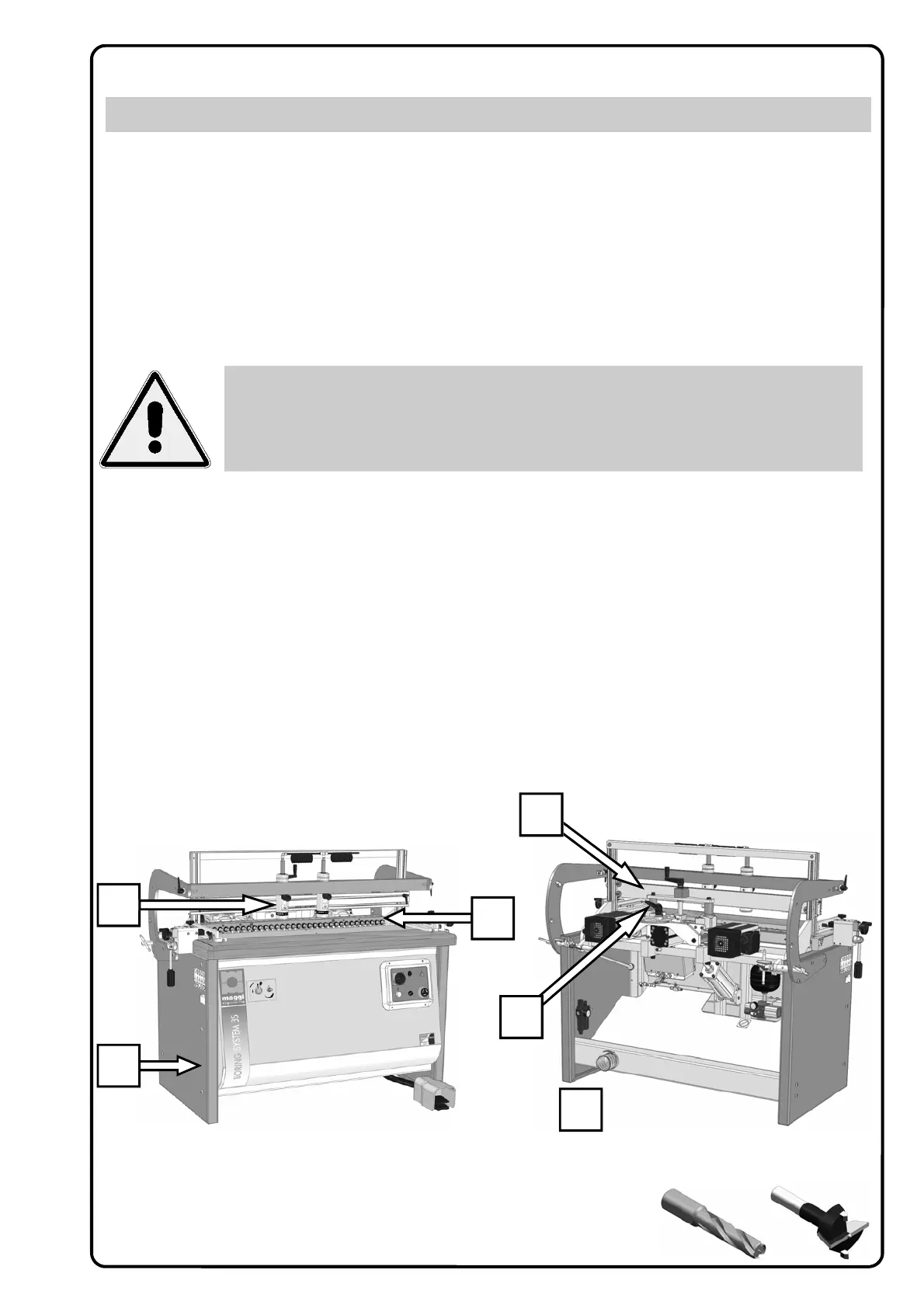
Fig. A Fig. B
3
1
2
5
6
4
3.1 USABLE TOOLS
D
rills for quick change spindles, 10 mm O. D. and 20 mm length shank (Fig. A )
Drills up to 40 mm O. D. can be used ( Fig. B )
3. MACHINE DESCRIPTION
Our boring machines have been manufactured to make holes on wood at a fixed distance of 32 mm (with
maximum accuracy) between each centre.
The head has its fulcrum on the machine table and it can be tilted up to a 90-degree angle. The operator place
the work piece on the working table, does some adjustments by using the pedal control, block the piece using
the clamp units and then start drilling.
The machine consists of:
1. a steel frame structure
2. one head group equipped with its trasmission system
3. clamp group for vertical blocking of the work piece
4. pneumatic system for head positioning and head feed
5. reference stops to obtain the same drilling distance from vertical to horizontal position
6. leaflet for positioning the spindle height, a mechanical counter and the “Spiral System” device ti regula-
regulate the hole depth from 0 mm to 85 mm
2. OPERATIVE NOTES
WOODWORKING MACHINES CAN BE DANGEROUS
1) A safe and correct use can be obtained by carefully and scrupulously following all the instructions con-
tained into this manual.
2) The machine must be used only by qualified users and personnel of age. The responsible for safety must
be sure that users of the machine have read and understood all the information contained into this man-
ual.
3) The personnel for both ordinary and extraordinary maintenance must be well prepared in mechanics and
electricity.
4) Keep off any parts in movement of the machine. Never touch the spindles and/or their respective parts in
movement of the machine.
5) Never put one working piece on top of another one. Correctly adjust the machine and then drill only one
working piece at time.
ANY ADULTERATION OR REMOVAL OF SAFETY PROTECTION DEVICES CAN CAUSE SE-
VERE DAMAGE. ANY REMOVAL, EXCLUSION OR MODIFICATION OF THESE DEVICES IS
STRICTLY FORBIDDEN. YOU MUST VERIFY AND GUARANTEE THE PERFECT RUNNING OF
SAFETY DEVICES BY MEANS OF PERIODIC CHECKS. ANY DEFECT OR PROBABLE DRAW-
BACK MUST BE IMMEDIATELY RESOLVED.