LT20A / LT30 Series
18 (E)
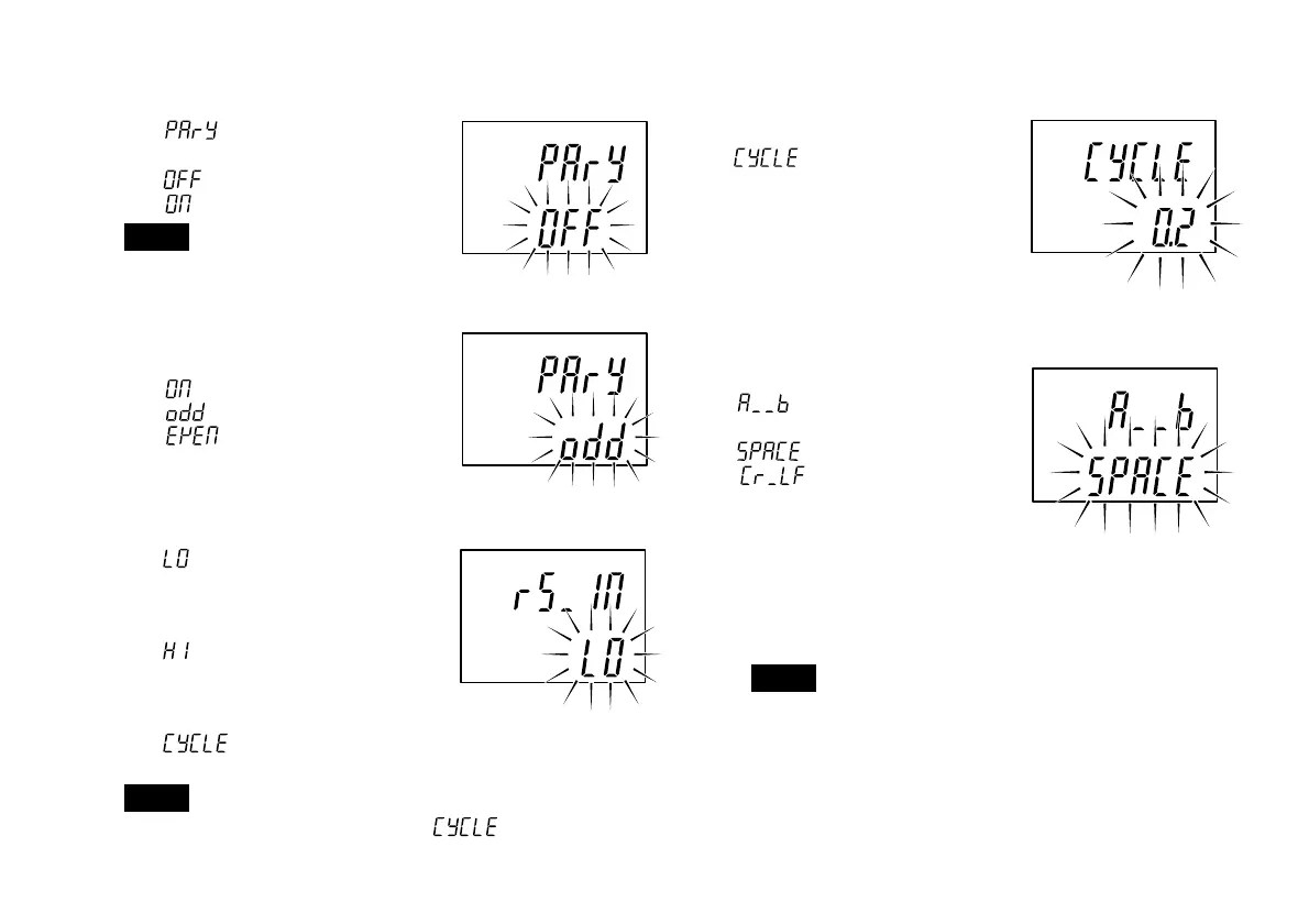
5. Setting the parity
is displayed and the
parity can be switched on or off.
: No parity
: Parity
Note
When the data length is set to 7 bits
in step 3, select “Parity”.
6. Selecting odd or even parity
Switches to this mode when
is chosen above.
: Odd parity
: Even parity
7. Selecting the function for the RS-TRG terminal
:Mode for inputting
mechanical contact
outputs (such as relay
and switch outputs).
:Mode for inputting
electronic circuit
outputs (such as
transistor outputs).
:To output at a set
interval.
Note
The RS-TRG input cannot be used when
has been selected.
8. Selecting the output time interval.
This mode is selected when
has been chosen in
step 7.
One of the following eight
intervals can be chosen.
0.2/0.5/1.0/5.0/10/30/60/300 s
9. Selecting the data transmission format
(2 channel models)
is displayed and one of
the following is chosen.
: format (a) given below
: format (b) given below
• To output from channel A –12.3456, and from
channel B 67.891:
(a) A–12.3456MB
+67.8910
C
R
L
F
(b) A–12.3456
C
R
L
F
B+67.8910
C
R
L
F
Note
M means a space.
factory-set
factory-set
factory-set
factory-set
factory-set
 Loading...
