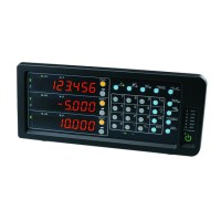
LT20A / LT30 Series
(E) 25
7 6 5 4 3 2 1 7 6 5 4 3 2 1
1 2 3 4 5 6 7
AB
FG +V 0V
DC IN
I/O connector BI/O connector A
Power input
connector
Common
I/O connector
7. I/O connector
The I/O connector on the rear panel of the counter unit has
functions for Go/No Go output based on the comparator
function, start input, pause input, RS-232C trigger input and
reset input.
7-1. Connector pin assignment
Rear of counter unit
• Use a shielded cable for connection to the FG pin on the
rear of the counter unit.
(Prepare a shield cable by yourself.)
Connector used : MC1.5/7-ST-3.5 (provided) made
by Phoenix Contact
Outer cover
Knitted shield
Cross section of the cable
Signal
(See “4-3. Function description”.)
I/O connector A
Pin Signal
IN/OUT Signal
No. name
1 GND –
2NC – Connection prohibited
3 RESET (A) IN Reset input (A CH)
4 LO (A) OUT Go/No Go output Low (A CH)
5 GO (A) OUT Go/No Go output Go (A CH)
6 HI (A) OUT Go/No Go output High (A CH)
7 GND –
I/O connector B (not provided for 1-channel models)
Pin Signal
IN/OUT Signal
No. name
1 GND –
2NC – Connection prohibited
3 RESET (B) IN Reset input (B CH)
4 LO (B) OUT Go/No Go output Low (B CH)
5 GO (B) OUT Go/No Go output Go (B CH)
6 HI (B) OUT Go/No Go output High (B CH)
7 GND –
 Loading...