LT20A / LT30 Series
28 (E)
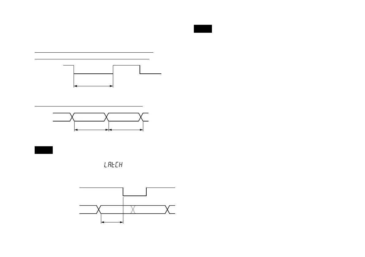
7-3. Signal timing
Start input to I/O connector (common) pins wr
Reset input to I/O connector A pin e, B pin e
I/O connector A pins rty B pins rty
Note
When the initial settings of the start/latch pins
w
and
r
of the
I/O connector (common) are
, the
“L”
(ON) signal will
hold the Go/No Go output and display value immediately
before.
I N
MIN. 0.1 ms
Sampling 50 µs
MAX. 0.2 ms
Go/No Go output
and display value.
wr
Note
High-speed sampling is performed where the Go/No Go
output is updated every 50 µs.
For this reason, when the count value is close to the
comparator setting value, the ON-OFF time may be output
repeatedly every 50 µs. Be careful because reception may
not be possible, depending on the sampling time on the
connected device side. In this situation, use the latch
function to first store the Go/No Go output and then receive
the result.
 Loading...
