LT20A / LT30 Series
16 (E)
factory-set
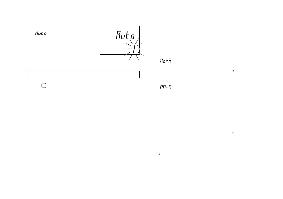
3. Automatic BCD output time interval
This mode is established when
has been set in step 2.
Select one of the eight time
intervals listed below.
1/2/4/8/16/32/64/128 ms
(See “8-2. Signal timing” for the
BCD input/output timing)
Initial settings are now complete for the BCD model.
Press
MODE
to return to the measuring state.
5-1-3. RS-232C model
(only LT20A-101C/201C, LT30-1GC/
2GC)
Proceeds to the next setting mode from “5-1-1. Basic
settings” step 4.
1. Setting the output data format
: Normal output
1st byte : Channel name (A or B)
2nd byte : Sign (“+” or “–”)
3rd to 9th bytes: Numerical data
(ex.12.3456)
: Outputting with measurement mode
information
1st byte : Channel name (A or B)
2nd byte : Current mode
(N: Current value,
P: Peak-to-peak value,
I : Minimum value,
A: Maximum value)
3rd byte : Unit (M: mm, I: inch)
4th byte : Sign (“+”
or “–”)
5th to 11th bytes
: Numerical data
(ex.00.0000)
: (“+” or space)

 Loading...