Magstim Rapid²
Operating Manual
© The Magstim Company Limited 7 MOP03-EN-03
3.1.1.8 Mainframe (8)
This Mainframe contains the circuitry that allows the stimulator to deliver energy as specified using the
UI.
3.1.1.9 Power Supply Unit (PSU) (9)
The PSU contains the electronic circuitry that powers the stimulator.
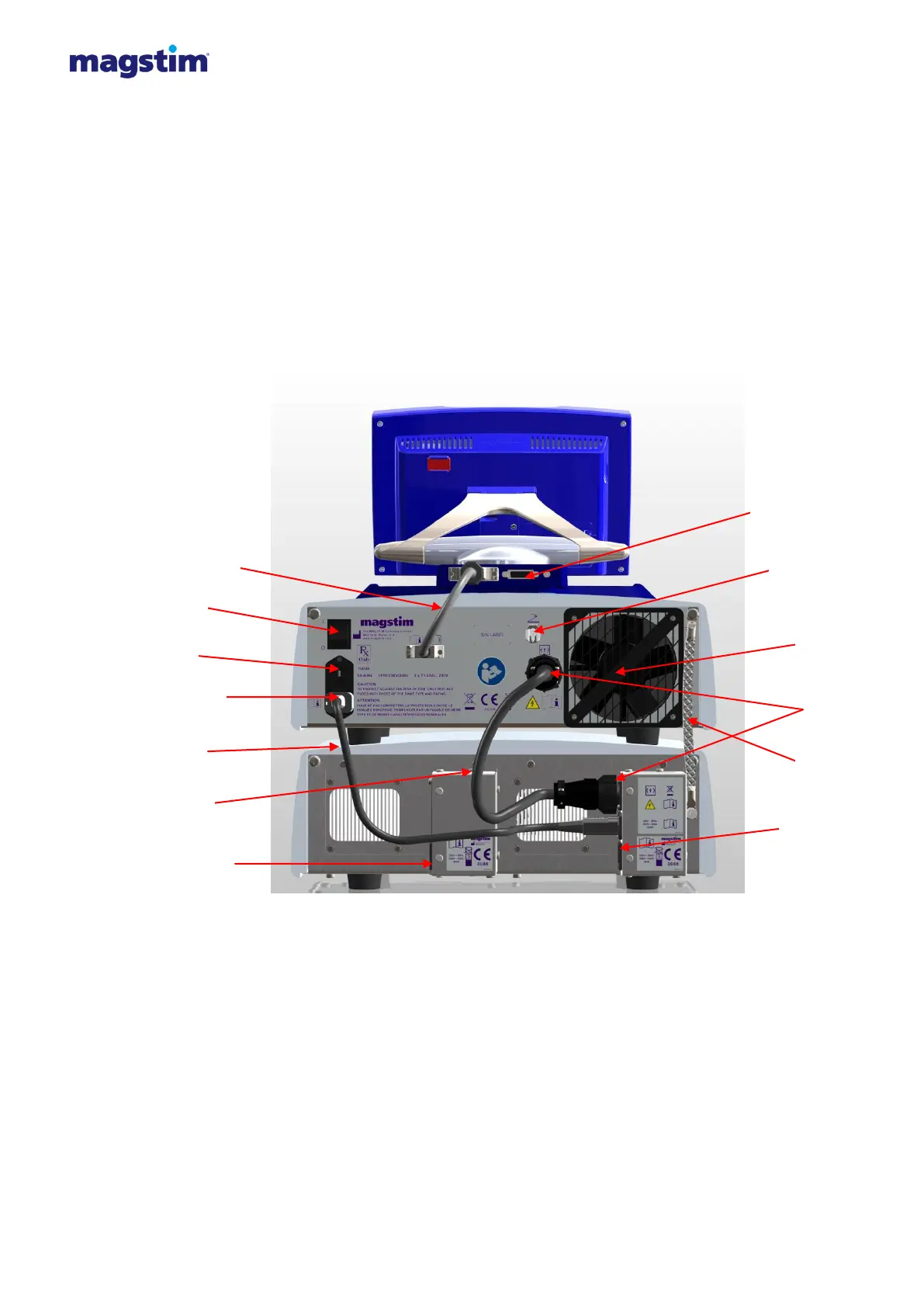
3.1.2 Rear view
Figure 3.4: Detailed rear panel of Super Rapid²
Note: The only difference between connections on the Standard Rapid² compared to the Super Rapid²
is the additional mains inlet on the left hand side of the PSU.
Note: 115V units are identical in appearance to the 230V units, with the exception of the
voltage/power rating labels sited to the rear
3.1.2.1 UI Cable* (1)
The UI cable connects the Rapid² UI to the Rapid² mainframe.



 To Next Page