Magstim Rapid²
Operating Manual
© The Magstim Company Limited 6 MOP03-EN-03
3.1.1.1 On/Off/Standby* (1)
This switch toggles the operational state of the Rapid
2.
3.1.1.2 Armed Indicator* (2)
The armed indicator illuminates when the unit is armed and high voltages are present on the system.
3.1.1.3 Power Indicator* (3)
The power indicator flashes when the Magstim Rapid² is in standby, and illuminates when the Magstim
Rapid² is on.
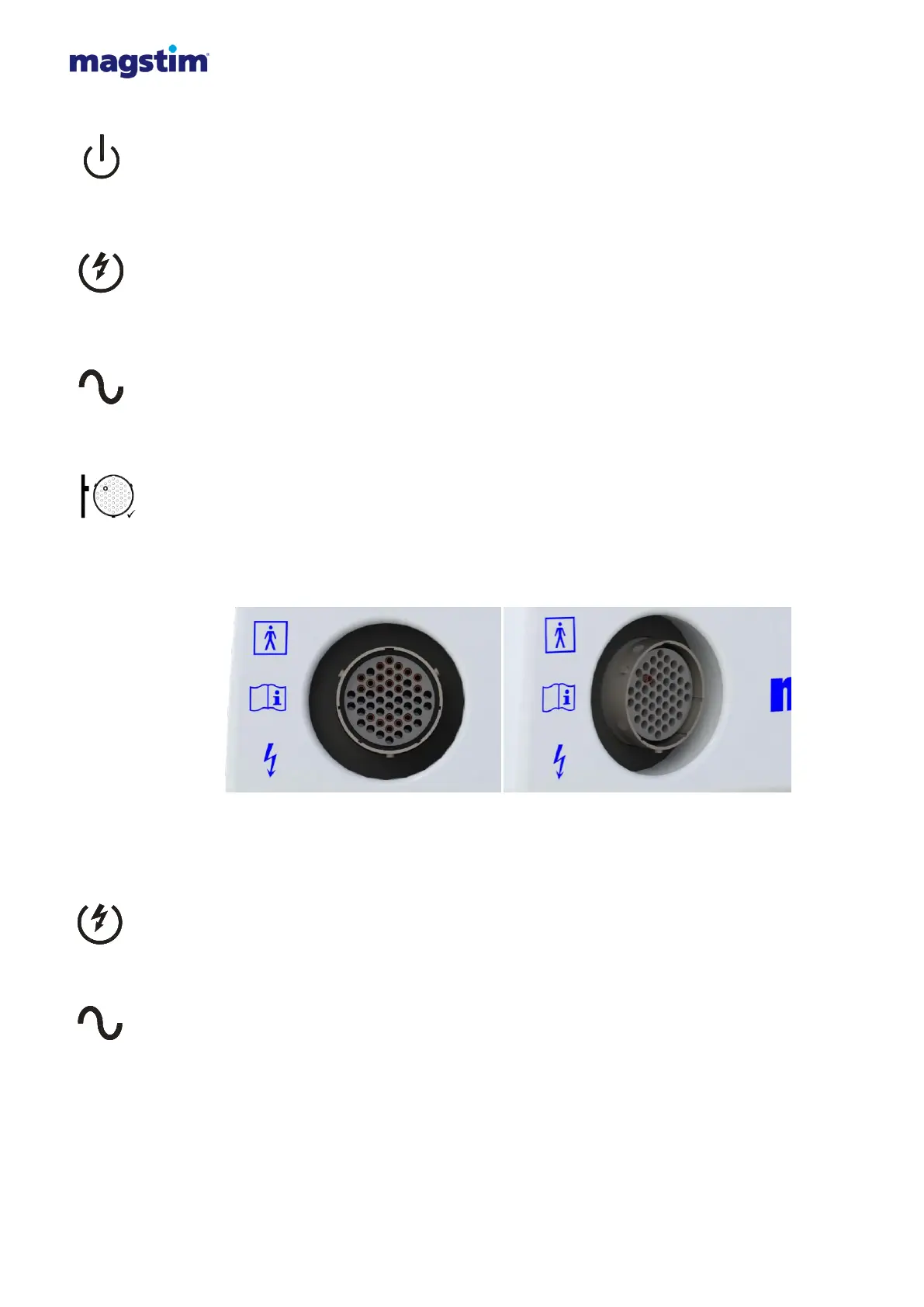
3.1.1.4 Coil Output Socket* (4)
This socket is used to connect the stimulating coil to the Magstim Rapid².
Note: It is normal for the pin indicated on the label to protrude from the coil socket. This is an
intentional design feature.
Figure 3.2: Coil output socket front view Figure 3.3: Coil output socket angled view
3.1.1.5 Armed/Fault Indicator* (5)
This LED is continuously illuminated when the Magstim Rapid
2
is armed and high voltages are present
on the system. This LED turns RED when a fault is detected in the PSU.
3.1.1.6 PSU Power Status Indicator* (6)
The PSU power indicator is OFF when the system is in standby or OFF. It is continuously illuminated
when the system is on.
3.1.1.7 Rapid² UI (7)
This is the interface by which the user controls the stimulator. See Section 3.3 for further details.