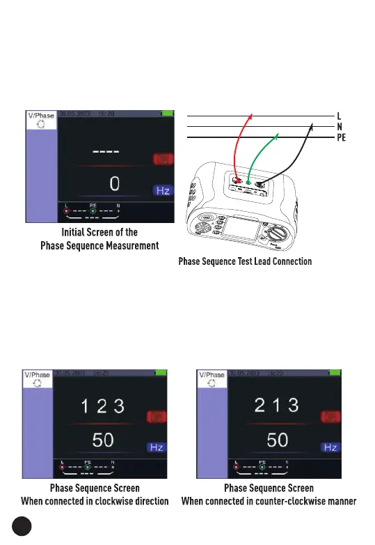
4.5. Using the Phase Sequence Function
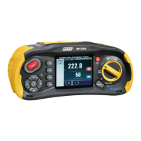
1. Turn the rotary switch to the Voltage Position.
2. Press F1 Button to make symbol is displayed.
3. Connect the test leads L1, L2, L3.
4. When the instrument is energized the sequence will be displayed
automatically.
• When the line conductors are connected in the correct sequence 1.2.3
and the symbol will appear as the Figure.
• However connected in the wrong sequence, 2.1.3 and the circle symbol
will change to the symbol displayed below.
26
 Loading...