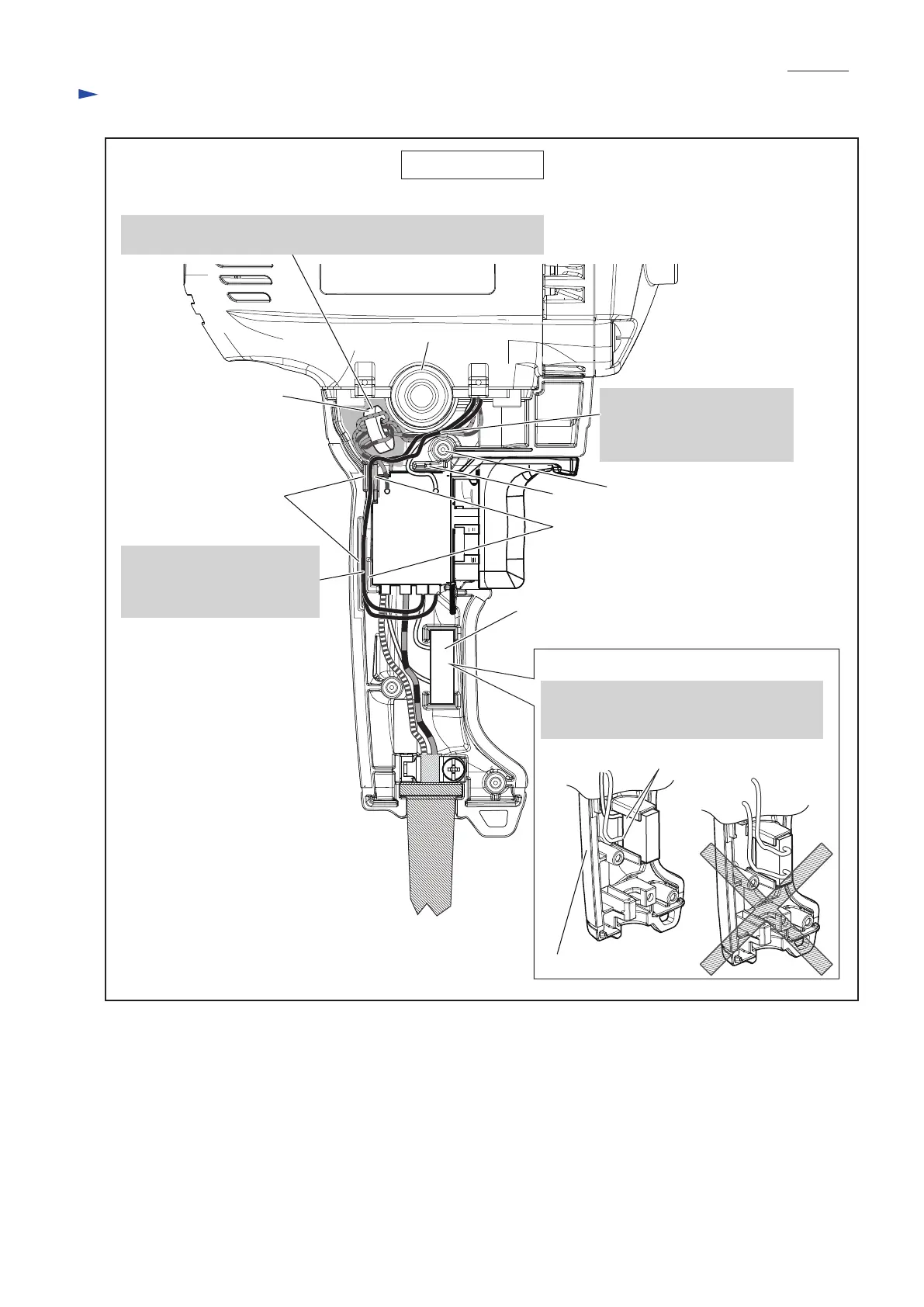
EasyManuals Logo

Makita DS4012 Technical Information

Makita DS4012
12 pages
To Previous Page IconTo Previous Page
Page #12 background imageLoading...
Page #12 background image
P 12/ 12
Wiring diagram
Wiring in Handle
Setting Noise suppressor
Noise suppressor
Handle L
Wire connected side of
Noise suppressor
Rib B
Rib A
Boss
Round wall
Face the wire connected side to Handle L
and assemble Noise suppressor to Handle L
as drawn in below left.
Fig. D-3
Inner wall
Line filter
Put Field lead wires between
Boss and Round wall.
Note: Be careful not to put
their wires on Rib A.
Put Line filter to the place designated in gray color when it is used.
When it is not used, put the slack of Lead wires to the place.
Put Field lead wires (black)
between Inner wall and Rib B.
Note: Be careful not to put
their wires on Rib B.
Switch

Other manuals for Makita DS4012

Questions and Answers:

Question and Answer IconNeed help?

Do you have a question about the Makita DS4012 and is the answer not in the manual?

Makita DS4012 Specifications

General IconGeneral
DrillingYes
Screwdriving-
Idle speed (max)600 RPM
Idle speed (min)0 RPM
Chuck capacity (max)- mm
Drilling diameter in wood (max)36 mm
Drilling diameter in steel (max)13 mm
Amperage8.5 A
Power sourceAC
Weight and Dimensions IconWeight and Dimensions
Depth340 mm
Width83 mm
Height390 mm
Weight2800 g

Related product manuals