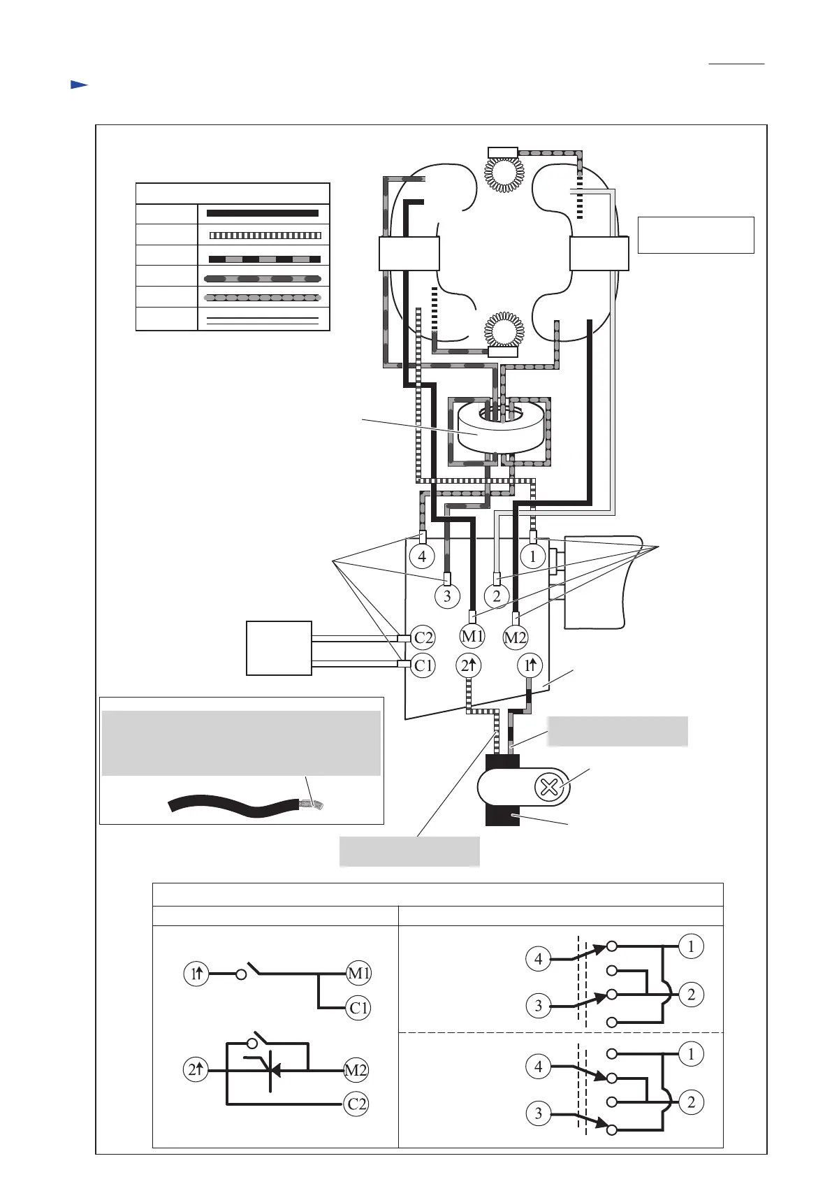
EasyManuals Logo

Makita DS4012 Technical Information

Makita DS4012
12 pages
To Next Page IconTo Next Page
To Previous Page IconTo Previous Page
Page #10 background imageLoading...
Page #10 background image
P 10/ 12
Fig. D-1
Circuit diagram
White
Orange
Blue
Brown
Color index of lead wires' sheath
Circuit diagram of Inside of the Switch
Circuit for ON / OFF Circuit for Forward / Reverse control
Black
Purple
Field
Switch
Power supply cord
Line filter
(if used)
AWG18
AWG18
AWG18
AWG18AWG18
AWG18
AWG20
AWG20
*AWG: American wire gauge
AWG18
AWG18
AWG18
When you connect Noise suppressor and Field
lead wires with Switch, solder the stripped wires
in advance, then clamp the soldering portions
with Splices.
Field view from
Armature fan side
Brush
holder
A
Brush
holder
B
in Forward
rotation
in Reverse
rotation
Strain relief
Splice
Splice
Noise
suppressor
(if used)
Black lead wire is used
for some countries.
White lead wire is used
for some countries.

Other manuals for Makita DS4012

Questions and Answers:

Question and Answer IconNeed help?

Do you have a question about the Makita DS4012 and is the answer not in the manual?

Makita DS4012 Specifications

General IconGeneral
DrillingYes
Screwdriving-
Idle speed (max)600 RPM
Idle speed (min)0 RPM
Chuck capacity (max)- mm
Drilling diameter in wood (max)36 mm
Drilling diameter in steel (max)13 mm
Amperage8.5 A
Power sourceAC
Weight and Dimensions IconWeight and Dimensions
Depth340 mm
Width83 mm
Height390 mm
Weight2800 g

Related product manuals