P 16/ 35
Repair
[3] DISASSEMBLY/ASSEMBLY
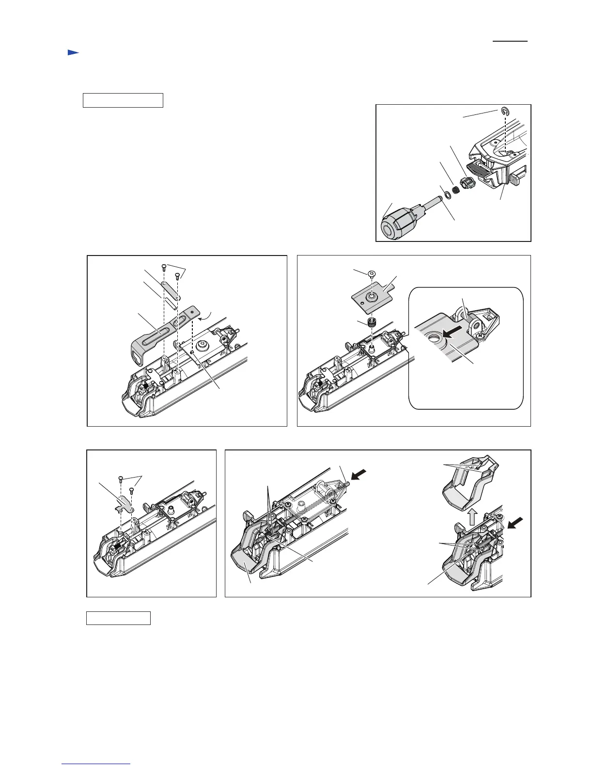
[3]-6. Positive lock mechanism of Turn base
DISASSEMBLING
ASSEMBLING
(1) Remove Stop ring E-7. (Fig. 47)
Grip 50, Compression spring 11, Flat washer 10 and Cam can be removed.
(2) Remove two CT4x16 Tapping screws and Plate from Turn base complete.
Miter lock plate B complete and Pin 6 are removed. (Fig. 48)
(3) Remove M6x14 H.S.Binding head screw then remove Miter lock plate in
the direction designated with black arrow. (Fig. 49)
(4) Remove CT4x16 Tapping screw (2pcs.) and Lock lever plate. (Fig. 50)
(5) While pushing Lock pin 6 in the direction of black arrow to remove
the ends of Pin 3 from the inner hooks of Lock lever, pick up Lock lever
in the direction of gray arrow shown in Fig. 51.
(6) Remove Pin 3 from Lock pin 6, then pull out Lock pin 6 from Lock lever
side.
Fig. 47
Fig. 48
Fig. 49
Fig. 50 Fig. 51
Take the disassembling step in reverse.
Stop ring E-7
Compression
spring 11
Flat washer 10
Grip 50
Turn base
Groove for Stop ring E-7
CT4x16 Tapping
screw (2pcs.)
Plate
Pin 6
Protrusion of Miter
lock plate B complete
Hole of Miter
lock plate A
Miter lock plate A
M5 Shoulder screw
Miter lock plate B
complete
Cam
Lock pin 6
Lock pin 6Lock lever
Compression
spring 6
Ends of Pin 3 passed
through Lock pin 6
Lock lever
plate
Miter lock plate can be pulled
out without removing M5
Shoulder screw.
M6x14 H.S.
Binding
head screw
Miter lock plate A
Compression
spring 13
CT4x16 Tapping
screw (2pcs.)
Inner hooks of
Lock lever
Ends of Pin 3 are
removed from
the inner hooks
of Lock lever

 Loading...