Do you have a question about the Makita PLANER 2040 and is the answer not in the manual?
Essential safety rules for operating power tools, including work area, apparel, and tool usage.
Information on matching voltage, proper grounding methods, and using adapters for safe operation.
Specific safety instructions for operating the planer, including blade handling and workpiece feeding.
Steps for safely removing the old cutter knives, including disassembling guards and drums.
Instructions on how to install new cutter knives and secure them properly for optimal cutting.
How to insert knives, use levellers, and ensure correct alignment for precise planing.
Fine-tuning knife height with levellers to achieve uniform planing across the workpiece.
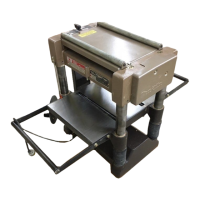
The Makita Planer Model 2040 is a robust and efficient woodworking tool designed for precise material removal and surface finishing. Its primary function is to plane wood, ensuring uniform thickness and smooth surfaces for various carpentry and construction projects. The planer is engineered to handle a wide range of stock sizes, making it versatile for both small-scale and larger woodworking tasks.
The planer is designed for ease of use and safety, incorporating several features to enhance the user experience. Before operation, it is crucial to read the instruction manual thoroughly to understand the tool's applications, limitations, and potential hazards. General safety precautions, such as keeping guards in place, removing adjusting keys and wrenches before starting, and maintaining a clean work area, are paramount. The tool should not be used in damp or wet environments and should be kept away from children.
To ensure optimal performance and safety, users are advised not to force the tool; it is designed to work best at its intended rate. Proper apparel, including non-slip footwear and protective hair covering, should be worn, and loose clothing or jewelry should be avoided to prevent entanglement with moving parts. Safety glasses are mandatory, and a face or dust mask should be used during dusty cutting operations. Securing the workpiece with clamps or a vise is recommended for stability and to free both hands for operation.
The planer's dimensional adjustment is straightforward. Users can release the thumb screw on the stopper ring and turn the crank handle clockwise to align the indicator plate with the desired finished dimension on the scale bar. One handle revolution adjusts the table by 3 mm (1/8"). The depth of cut is determined by the stock width, with specific guidelines provided for maximum depth based on the wood's width. For thicker cuts, it is advisable to make multiple passes rather than overloading the planer.
Stock feed is managed by aligning the stock with the top of the table. If the stock is too thick, the table can be lowered using the crank handle to reduce the cut size. Precautions for feeding include avoiding outsized stock to prevent abnormal wear on rubber rollers and maintaining a level feed to ensure even cutter action and roller wear. The planer also features convenient return rollers on top, making it easy to return cut stock to the front side.
For repetitive tasks, the stopper regulating depth allows users to plane numerous workpieces to the same thickness by setting the stopper ring to the desired dimension. Care should be taken not to force the crank handle excessively, which could move the stopper ring. A key safety switch is integrated, requiring the key to be inserted to switch on the machine. The key can be removed while the switch is in the "ON" position, but the tool can still be switched off without it. When unattended, the machine should always be "OFF" and unplugged.
Regular maintenance is essential for the planer's longevity and safe operation. Before any inspection or maintenance, the tool must be switched off and unplugged from the power source.
Changing cutter knives is a critical maintenance task. First, the planer must be unplugged. To remove the knives, the pan head screws on the set plates are loosened with a screwdriver, and the set plates are swung open. The chip guard is removed, the lever is lifted and swung 180 degrees, and the knob on the belt guard side is used to align the cutter drum. The lever is then released to make the drum stationary. The 8 hex bolts are removed with the provided socket wrench, and the drum cover (cutter retaining plate) is taken off. The end of the socket wrench handle can be used to push the cutter out slightly. The lever is raised again to make the drum stationary at the position shown in Fig. 7, and then the cutter knife is removed.
For cutter knife installation and height adjustment, the knife is inserted so its holes align with those on the drum. Wooden levellers are placed on each end of the knife edge and pressed down until they contact the main frame surface, just above the hex bolt holes. The cutter drum is fixed in the position shown in Fig. 6, the drum cover is attached, and the hex bolts are fastened securely. Bolts should be tightened gradually and evenly before applying the final tightening torque to prevent the knife from moving. After securing the lever at the position it was in when the chip guard was raised, the lever is set on top, pressed down gently, and the cutter drum is turned in the arrow direction. The leveller should move consistently when placed over either end of the same knife (approximately 5-6 mm or 3/16″ – 1/4″). After adjusting both knives, the chip guard and auto-planer guard (chip cover) are replaced and secured in their original positions.
Adjusting various components like the bed rollers is also part of maintenance. Although factory-adjusted, if adjustment is needed, the pan head screw for each roller under the table is loosened. A screwdriver is used to rotate the groove on the roller adjuster within 180 degrees on the four roller axes. Rotating the groove upwards raises the bed roller, while turning it downwards lowers it. This adjustment should be performed on both sides for even roller adjustment. A caution is given that if the two groove positions on one roller face different directions, the stock may twist. Also, if rollers protrude too much (more than 0.1-0.3mm), notching may occur on the planed surface. The small screw should be tightened after adjustment.
Extension roller adjustment involves gently loosening the hex bolts, setting a rule or yardstick on the table surface, and adjusting the roller arm to be slightly higher than the table. The hex bolts are then securely tightened so the roller arm surface is at 90° to the column.
Infeed/outfeed rollers are factory-adjusted, but if adjustment is required, a straight and level piece of wood is placed on the outfeed table. The crank handle is turned to raise the table until the wood contacts the main frame, then turned a half-turn counterclockwise to lower the table slightly. The wood is inserted under the outfeed roller, and the right and left height adjusting screws are adjusted so the outfeed roller contacts the wood evenly. The infeed roller is adjusted similarly. Turning the height adjusting screw one turn clockwise lowers the roller by 3 mm (1/8").
Carbon brushes should be regularly checked and replaced when they wear down to the limit mark. They should be kept clean and free to slip in their holders, and both brushes should be replaced at the same time with identical carbon brushes. To replace them, a minus screwdriver is inserted into the holes for carbon brush changeover on the planer base, the brush holder cap is removed, and the worn brush is taken out. New carbon brushes are inserted, and the brush holder caps and holders are reinstalled.
Cleaning involves brushing off dirt, chips, and foreign matter adhering to roller surfaces. Care must be taken to prevent water or oil from entering the motor. Periodic lubrication is also necessary, which includes oiling the chain (after removing the chain cover), the column moving parts (contact areas), and the crank handle with machine oil. Lubrication should only be performed when the tool is not operating.
To maintain product safety and reliability, any repairs, maintenance, or adjustments should be performed by Makita Authorized or Factory Service Centers, using only Makita replacement parts.
| No. of Knives | 2 |
|---|---|
| Planing Width | 204 mm |
| Planing Depth | 3 mm |
| Max. Planing Width | 204 mm |
| Max. Planing Depth | 3 mm |