28
NO
NO
OK
1
Tester (AC 20 V)
2
B
VL
RS
VR
BL
N
GR
B
VL
RS
VR
R
N
GR
L I G H T I N G S Y S T E M
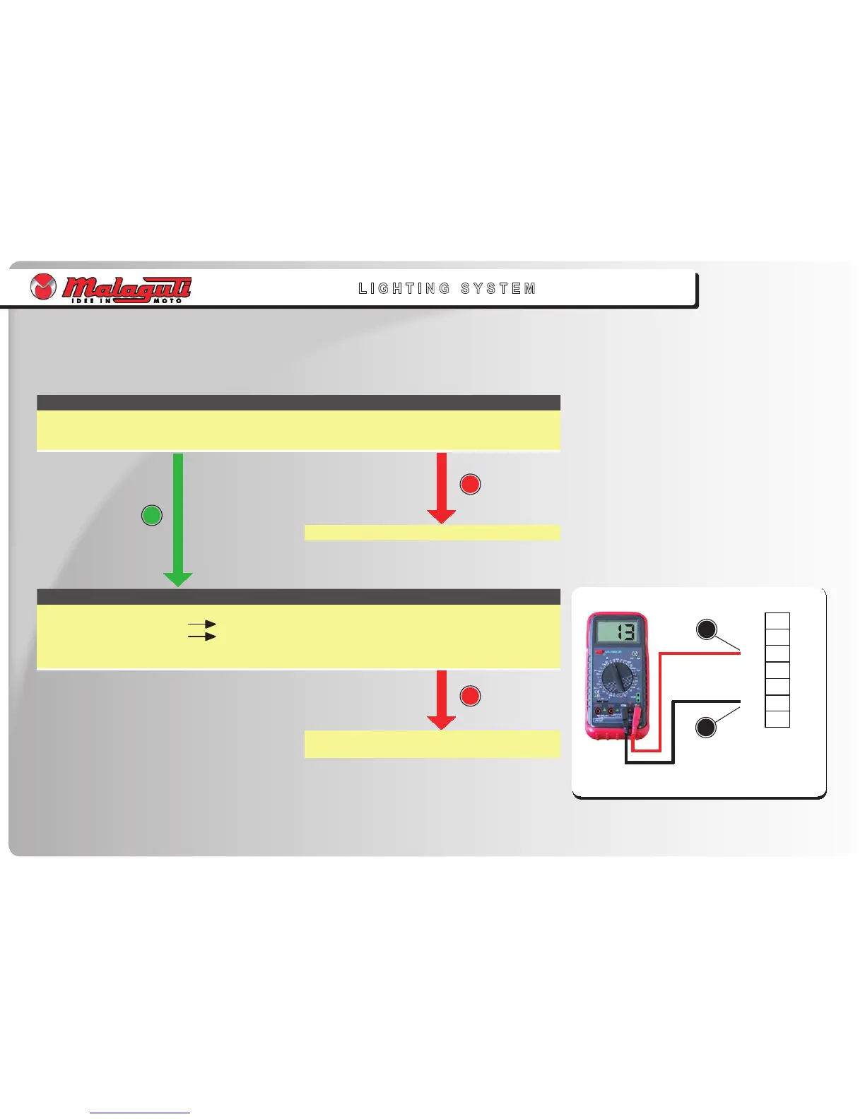
THE INSTRUMENT BOARD LIGHT INDICATOR LIGHT DOES NOT WORK
Check:
1. Continuity of light bulb and relative coupling
Connect Tester (Ω)
•
•
•
2. TVoltage delivered to instrument board
Connect Tester (20 V AC) to instrument board connector, as follows:
Terminal (+) of Tester Pink cable (1)
Terminal (-) of Tester Black cable (2).
Voltage delivered to instrument board: > 12 V
•
•
•
•
•
Pink
 Loading...