2
19
MHT 10120 L M
Series
1
1
6
6
-
-
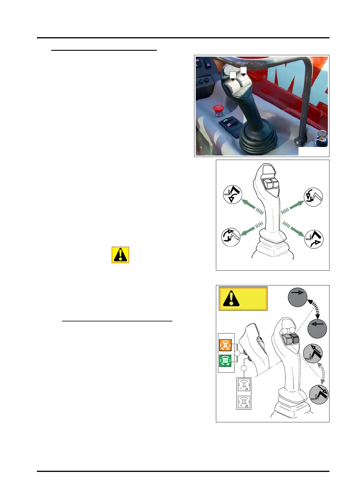
HYDRAULIC MOVEMENT CONTROLS
The truck is equipped with a one lever manipulator with
proportional electro-hydraulic servo control placed on the
operator's right and composed of two proportional button
“A” and “B” (Fig.16).
- To lift the load, pull the control lever back (Fig.16/1).
- To lower the load, pull the control lever forward
(Fig.16/1).
- To tilt the forks down pull the control lever to the right
(Fig.16/1).
- To raise the fork back into position, pull the control lever
to the left (Fig.16/1).
- To extend the telescopic arm, pull the “A” proportional
button up (Fig.16/2).
- To retract the telescopic arm, pull the “A” proportional button
down (Fig.16/2).
- To operate the optional function, pull the “B” proportional but-
ton up or down (Fig.16/2).
- to activate the 2
nd
or 3
rd
optional at the top of the boom or the
movements of an accessory (if equipped) press button “C”
and use roller “B” to carry out the required movements
(Fig.16/2).
N. B. button “C” activates the two optional outputs at the top of
the boom alternately.
Button “D” selects the main optional.
Never attempt to modify the hydraulic pressure of the system.
In case of malfunction, contract your agent or dealer.
ANY MODIFICATION WILL CASE THE WARRANTY TO
BECOME
NULL AND VOID.
1
1
6
6
/
/
A
A
-
-
OPTIONAL CIRCUIT DECOMPRESSION
This operation must be carried out each time it is necessary to
connect or disconnect a supplemental accessory to the fork-lift
truck.
1) Turn off the engine and place the ignition key 7 in position
“I”.
2) Rotate roller “B” forwards and backwards (pushbutton “17”
pressed and red LED On see page 20), and press button “C”
to activate the 2
nd
/3
rd
optional at the top of the boom and act
on roller “B”.
When the operation has been completed, the optional circuit
has been depressurised; therefore, it will be easier to connect
and disconnect the rapid fittings on the top of the arm.
N. B. The operation should be performed immediately after
turning off the engine, and for no more than 3 seconds for each
button.
FIG. 16
Fig. 16/1
A
B

 Loading...