3-36
G7 - LIFT TRUCK
SLING
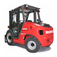
- Take into account the position of the lift truck gravity center for lifting (fig. G7/1).
A = 970 mm B = 830 mm
MSI 20 T Série 2-E3 MSI 20 T BUGGIE Série 2-E3
A = 1040 mm B = 760 mm
MSI 25 T Série 2-E3 MSI 25 T BUGGIE Série 2-E3
A = 1120 mm B = 680 mm
MSI 30 T Série 2-E3 MSI 30 T BUGGIE Série 2-E3
A = 1160 mm B = 640 mm
MSI 35 T Série 2-E3 MSI 35 T BUGGIE Série 2-E3
A = 960 mm B = 840 mm
MH 20-4 T BUGGIE Série 2-E3
A = 1020 mm B = 780 mm
MH 25-4 T BUGGIE Série 2-E3
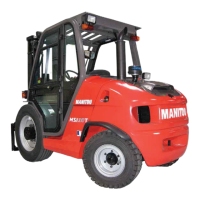
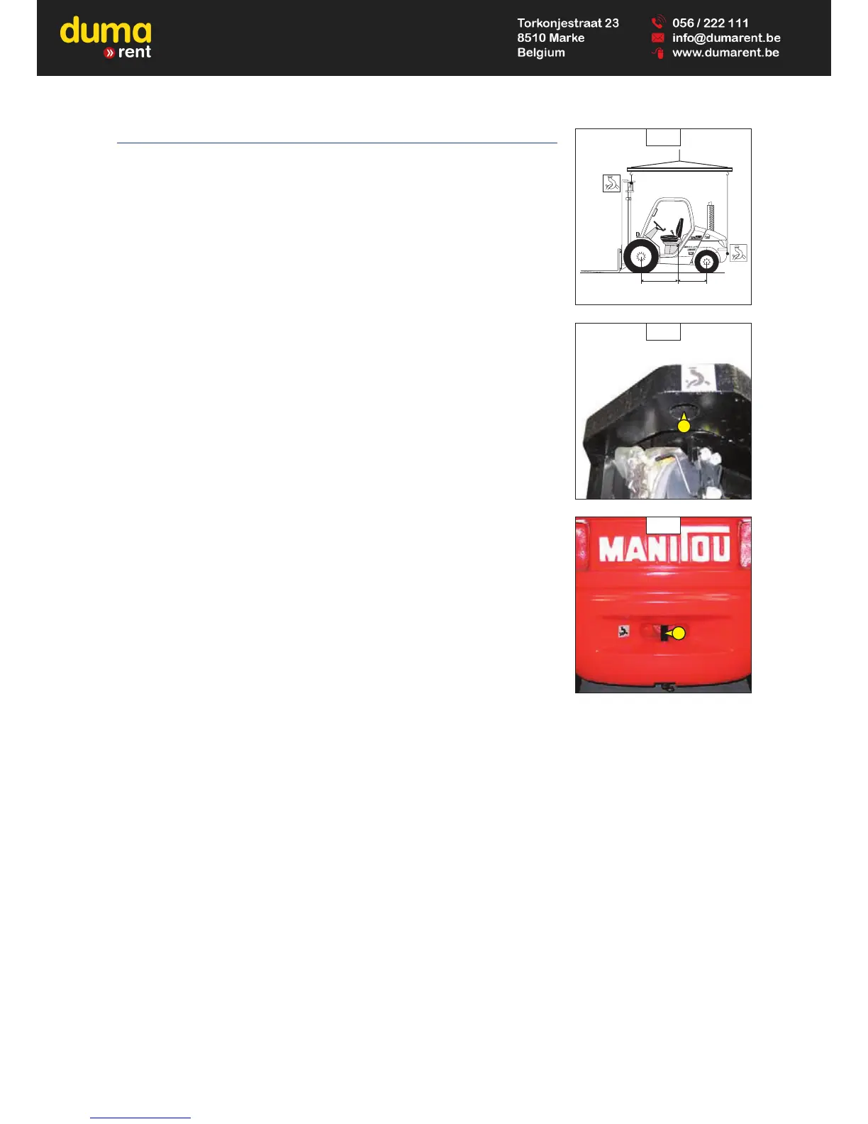
- Place the hooks in the fastening points provided (fig. G7/2 and G7/3).
 Loading...