3-55
IT EN
648870 IT-EN-PL (04/05/2015)
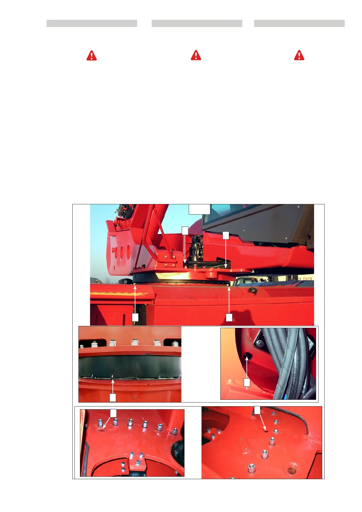
D6 - Check the bolts that fix the fifth
wheel coupling and turret
Raise the jib and place the jib safety wedge
on the rod of the lifting cylinder (see: 1 -
OPERATING AND SAFETY INSTRUCTIONS:
LIFT TRUCK MAINTENANCE INSTRUCTIONS).
Park the truck on a flat surface with the
thermal engine off, without a load or stress
from external sources.
Visually check to make sure that the bolts
are correctly torqued (Fig.D6 fifth wheel
coupling and Fig.D6 turret). If necessary,
tighten the bolts to the indicated torque
values:
Driving torque 346 Nm / 35.3 Kgm.
Pass through a hole above the turret to
tighten the bolts that fix the fifth wheel
coupling to the chassis (see fig.D9).
Pass through a hole under the chassis of
the machine to tighten the turret screws
(see fig.D6)
2
2
1
2
1
2
1
1
D6
D6 - Controllare i bulloni di fissaggio
ralla e torretta
Sollevare il braccio e collocare il cuneo di
sicurezza sullo stelo del martinetto di solle-
vamento (vedere: 1 - ISTRUZIONI E NORME DI
SICUREZZA: ISTRUZIONI DI MANUTENZIONE
DEL CARRELLO ELEVATORE).
Posizionare il carrello su di una superficie
piana con il motore termico spento, senza
carico e sollecitazioni di forze esterne.
Effettuare un controllo visivo del corretto
serraggio dei bulloni (D6) ralla e torretta e
in caso di anomalie serrare i bulloni secon-
do i valori di coppia descritti :
Coppia di serraggio 346 Nm / 35.3 Kgm.
Per stringere i bulloni della ralla che la
fissano al telaio, occorre passare tramite un
foro al di sopra della torretta “1” (D6).
Per stringere le viti che fissano la ralla alla
torretta occorre passare tramite un foro al
di sotto del telaio macchina “2” (D6).
PL
D6 - Kontrola śrub mocujących obrot-
nicę i wieżyczkę
Podnieść wysięgnik i umieścić klin zabezpiec-
zający na tłoczysku siłownika podnoszenia
(patrz: 1 - INSTRUKCJE I ZASADY DOTYCZĄCE
BEZPIECZEŃSTWA: INSTRUKCJE DOTYCZĄCE
KONSERWACJI WÓZKA PODNOŚNIKOWEGO).
Ustawić wózek z wyłączonym silnikiem spa-
linowym, bez obciążenia i bez działania sił
zewnętrznych, na płaskim podłożu.
Sprawdzić wzrokowo, czy śruby (D6) obrot-
nicy i wieżyczki są prawidłowo dokręcone i
w przypadku stwierdzenia nieprawidłowoś-
ci dokręcić je momentem o wymaganej
wartości podanej poniżej:
Moment dokręcenia 346 Nm / 35,3 kGm.
W celu dokręcenia śrub dwustronnych,
które mocują obrotnicę do ramy, konieczne
jest "przejście" przez otwór nad wieżyczką
“1” (D6).
W celu dokręcenia śrub, które mocują
obrotnicę do wieżyczki, konieczne jest
"przejście" przez otwór pod ramą maszyny
“2” (D6).
648870 IT-EN-PL (04/05/2015)