Grove Published 04-04-2017, Control # 446-09 4-15
RT770E OPERATOR MANUAL SET-UP AND INSTALLATION
e. Install the attachment pin into the anchor and
attachment fittings on the left side of the base
section.
f. Lower the boom and remove the rope from the tip of
the extension.
NOTE: Refer to Setting the Folding Swingaway Offset,
page 4-17 to obtain a 25 or 45 degree offset with
the swingaway.
27. Remove the cable retainer pins and clip pins from the tip
of the extension base section or extension fly section.
NOTE: For zero (0) degree offset, leave the mast
assembly in the stowed position.
28. Remove the mast assembly clip pin and pin from the
stowed position on the extension and raise the mast
assembly to an upright position. Install the pin and clip
pin. Remove the cable retainer pin and clip pin from the
mast.
NOTE: The hoist cable is not routed over the base
extension sheave when using the fly extension.
29. Route the hoist cable over the mast sheave, the rollers
on the adapter, the roller on the fly extension, and the
sheave on the extension tip. Install the cable retainer
pins and clip pins.
NOTE: Do not reeve hoist cable through sheaves on the
main boom nose.
30. Rig the hoist cable.
Stowing the Boom Extension
NOTE: The boom extension must be set at the zero (0)
degree offset. Refer to Setting the Folding
Swingaway Offset, page 4-17.
NOTE: If so equipped, the folding fly section must be
stowed on the side of the base section.
1. Fully retract the boom and swing it over the front.
2. Set the boom manual/automatic mode selector switch to
the AUTO position.
3. Set the boom A/B mode selector switch to the B mode.
4. Lower the boom, then extend the boom only enough to
disengage the spring loaded boom stop block.
5. Pull down on the handle to disengage the spring loaded
boom extension stop block (Figure 4-14). Place the end
of the handle in the retainer plate.
6. Fully retract the boom.
NOTE: When the boom retracts, the handle will be
released allowing the stop block to engage when
the boom is extended.
NOTE: The length indication on the rated capacity limiter
(RCL) will display 0 (zero) when the spring-loaded
stop block is in the working position (engaged) and
the boom is fully retracted. The RCL may display a
negative dimension when the stop block is
retracted (disengaged) and the boom is fully
retracted during the process of stowing and
erecting the boom extension.
7. Lower the boom to minimum elevation.
8. Remove the cable retainer pins and clip pins from the
swingaway tip and mast assembly. Remove the hoist
cable from the extension sheave and or mast. Install the
cable retainer pins and clip pins.
9. Remove the mast assembly pin and clip pin securing the
mast in the upright position. Lay the mast over to the
stowed position and install the mast assembly pin and
clip pin.
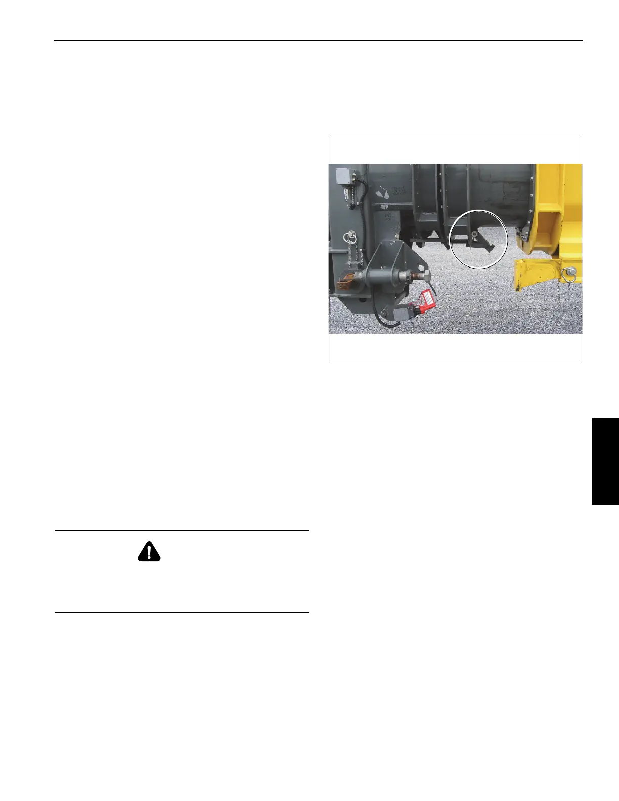
10. Disconnect RCL cable.
a. Remove connector (1, Figure 4-15) from junction
box on boom nose.
DANGER
During disengagement of the stop block, extend the boom
only enough to free the block. Extending the boom too far
will cause the base extension to slide off the guide ramps
and allow the extension to swing.
 Loading...


