Grove Published 04-04-2017, Control # 446-09 3-3
RT770E OPERATOR MANUAL OPERATING CONTROLS AND PROCEDURES
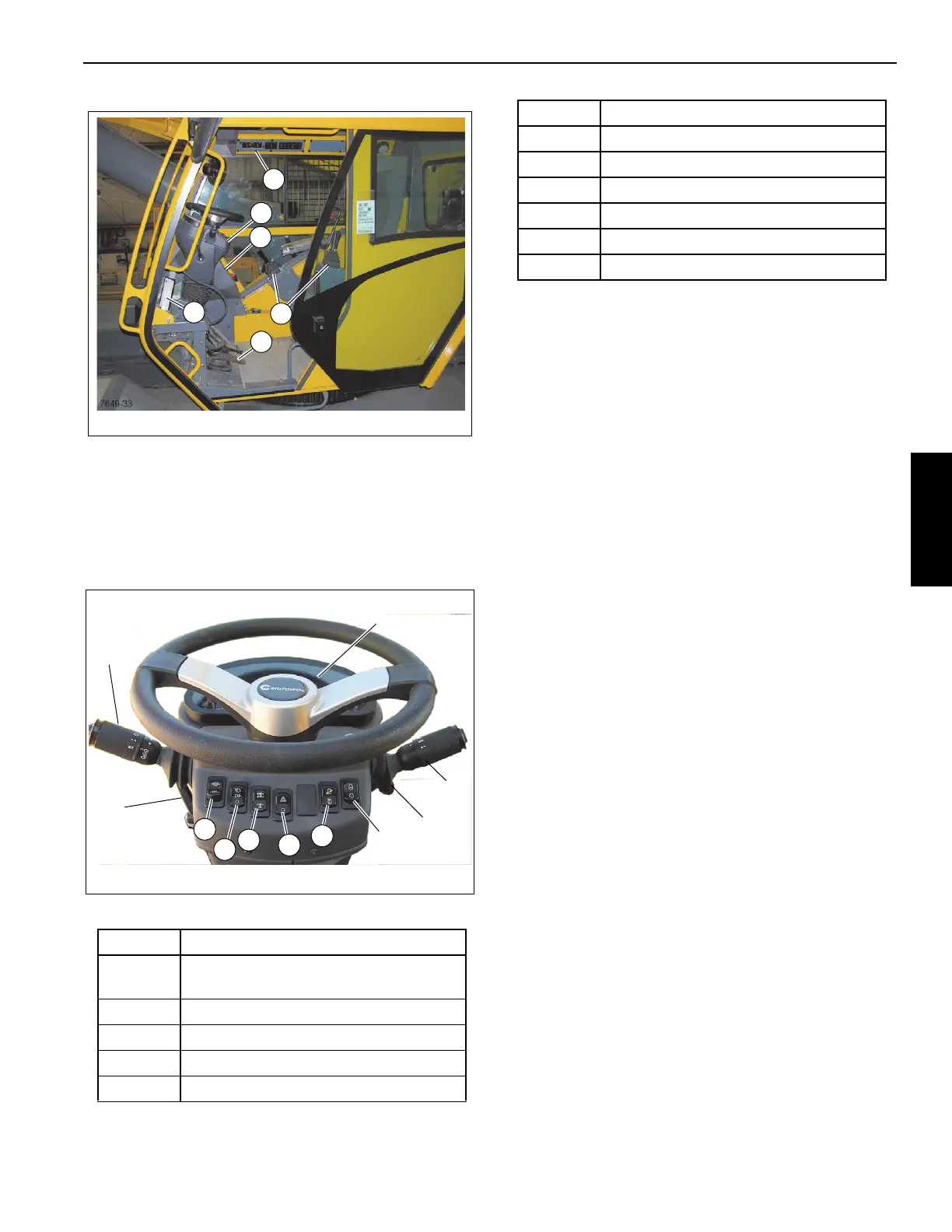
STEERING COLUMN
The steering column assembly in Figure 3-2 is a pedestal
style tilt and telescoping steering column. It has the ability to
tilt forward 30° or be raised vertically approximately 2.5
inches. It also includes the ignition switch and the CAN bus
gauge display (11) (Figure 3-2).
Figure 3-2 Item Numbers
Turn Signal Lever and Windshield Wiper/
Washer/Headlight /Horn Controls
The Turn Signal Lever and Windshield Wiper/Washer
Controls (1) (Figure 3-2) are located on the left side of the
steering column. Pushing the turn signal lever down causes
the left front and left rear turn signals to flash. Pushing the
turn signal lever up causes the right front and right rear turn
signals to flash.
The windshield wiper switch is incorporated in the turn signal
lever. The knob of the lever has three positions: O, I, and II.
Pushing the button in the end of the knob energizes the
windshield washer pump to spray washer fluid on the
windshield. Positioning the knob to I operates the wiper at
low speed and positioning the knob to II operates the wiper
at high speed. Positioning the knob to O turns the wiper
motor off and automatically returns the wiper to the parked
position.
Pushing the small button on the end of the lever sounds the
horn.
Steering Column Adjustment Lever
The steering control column can be rotated forward
approximately 30° and raised approximately 2.5 inches.
Rotate the steering column adjustment lever (2) (Figure 3-2)
counterclockwise to release the steering column for
adjustments; rotate the steering column adjustment lever (2)
(Figure 3-2) clockwise to lock the steering column in place.
Park Brake Control Switch
The Park Brake Control Switch (3) (Figure 3-2) is located on
the front of the steering column. This two-position rocker
switch (ON/OFF) is used to apply and release the parking
brake on the drive line. The red Park Brake Indicator light on
the steering column is illuminated when the pressure switch
in the brake release system is activated and the brake is
applied.
Headlights Switch
The Headlights Switch (4) (Figure 3-2) is located on the front
of the steering column. This three-position rocker switch
(OFF/Park/Headlight) controls operation of the instrument
lights, switch LED’s, and the marker lights on the front, rear,
Item Description
1
Turn Signal Lever and Windshield Wiper/
Washer/Headlight /Horn Controls
2 Steering Column Tilt Lever
3 Park Brake Control Switch
4 Headlights Switch
5 Drive Axle Selector Switch
FIGURE 3-2
7649-1
1
2
4
3
8
9
6
5
7
10
11
6 Hazard Lights Switch
7 Engine Diagnostic/Speed Control Switch
8 Increment/Decrement Switch
9 Ignition Switch
10 Transmission Shift Lever
11 Gauge Display
Item Description

 Loading...


