OPERATING CONTROLS AND PROCEDURES RT770E OPERATOR MANUAL
3-6 Published 04-04-2017, Control # 446-09
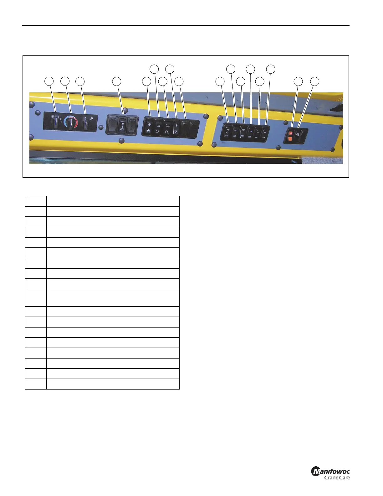
OVERHEAD CONTROL PANEL
Figure 3-4 Item Numbers
Heater/Air Conditioner Fan Switch
The Heater/Air Conditioner Fan Switch (1, Figure 3-4) con-
trols the cab fan’s speed. Fan speed controls the volume of
heated air output (or cooled air output) of the fan. Settings
are off, low speed, medium speed, and high speed.
Heater Control Switch
The Heater Control Switch (2, Figure 3-4) controls intensity
of heating temperature. Turn the switch to the right (clock-
wise) to open the valve for heat. (Heat comes from heated
fluid going through the heater coil.) Turn the switch to the left
(counterclockwise) to close the valve to stop fluid flow and
minimize heat.
Air Conditioner Switch
The Air Conditioning Switch (3, Figure 3-4) controls the oper-
ation of the optional air conditioning system. Settings are off
(O) and on (I).
Skylight Wiper Switch
The electrically-operated Skylight Wiper is installed to
remove moisture from the skylight. The Skylight Wiper is
controlled by the Skylight Wiper Switch (4, Figure 3-4). This
is a 3 position switch OFF/LOW speed/HIGH speed.
Panel Dimmer Switch
The Panel Dimmer Switch (5, Figure 3-4) controls the
lighting for the overhead heater/air conditioning controls and
the Transmission Oil Temperature Gauge (7, Figure 3-10),
push the switch to increase or decrease the panel lighting.
Work Lights Switch
The Work Lights Switch (6, Figure 3-4) controls the crane’s
work lights mounted on the bottom front of the superstructure
cab. Press the top of the switch to turn on the work lights.
Press the bottom of the switch to turn off the work lights.
FIGURE 3-4
8126-1
6
4
5
1
2
3
7
9
8
10
11
12
13
14
15
16 17
Item Description
1 Heater/Air Conditioner Fan Switch
2 Heater Control Switch
3 Air Conditioning Switch
4 Skylight Wiper Switch
5 Panel Dimmer Switch
6 Work Lights Switch
7 Boom Light Switch (Optional)
8 Crane Function Power Switch
9
EXHAUST System Cleaning Switch (Tier 4
engine only)
10 Boom Section 1/Section 2 Selector Switch
11 Boom Section 1/Section 2 Indicator
12 Boom Manual/Automatic Mode Selector Switch
13 Boom Manual/Automatic Mode Indicator
14 Boom A/B Mode Selector Switch
15 Boom A/B Mode Indicator
16 Recovery Mode Switch
17 Recovery Mode Indicator