Grove Published 04-04-2017, Control # 446-09 3-7
RT770E OPERATOR MANUAL OPERATING CONTROLS AND PROCEDURES
Boom Lights Switch (Optional)
The Boom Lights Switch (7) (Figure 3-4) is located on the
side display panel. This two-position rocker switch (ON/OFF)
controls operation of the boom flood lights. Press the top of
the switch to turn on the boom lights, press the bottom of the
switch to turn the lights off.
Crane Function Power Switch
The Crane Function Power Switch (8) (Figure 3-4) is located
on the side display panel. This two-position (ON/OFF) rocker
switch permits the operator to disconnect power from the
crane functions controlled by the hydraulic remote
controllers on the armrests. Positioning the switch to OFF
prevents inadvertent operation of functions due to bumping
the controllers while roading or any other operation. With the
switch in the OFF position, operation of the high speed hoist
is also prevented.
Hoist Rotation Indicator Display
The display is located in the front overhead panel Figure 3-9.
Refer to Hoist Rotation Indicator Display, page 3-7 for more
information.
EXHAUST System Cleaning Switch (Tier 4
Engines Only)
The Engine DPF (Diesel Particulate Filter) Switch (9)
(Figure 3-4) is located on the right side of the overhead
control panel. This switch is a three position switch, Inhibit
Regen/Permit Regen/Start Regen. Press this switch to start
engine regeneration or to disable regeneration:
• Start Regeneration
(7649-10)
• Inhibit Regeneration (7649-11)
To manually regenerate, set the crane parking brake, the
crane transmission must be in neutral and have all pedals
released.
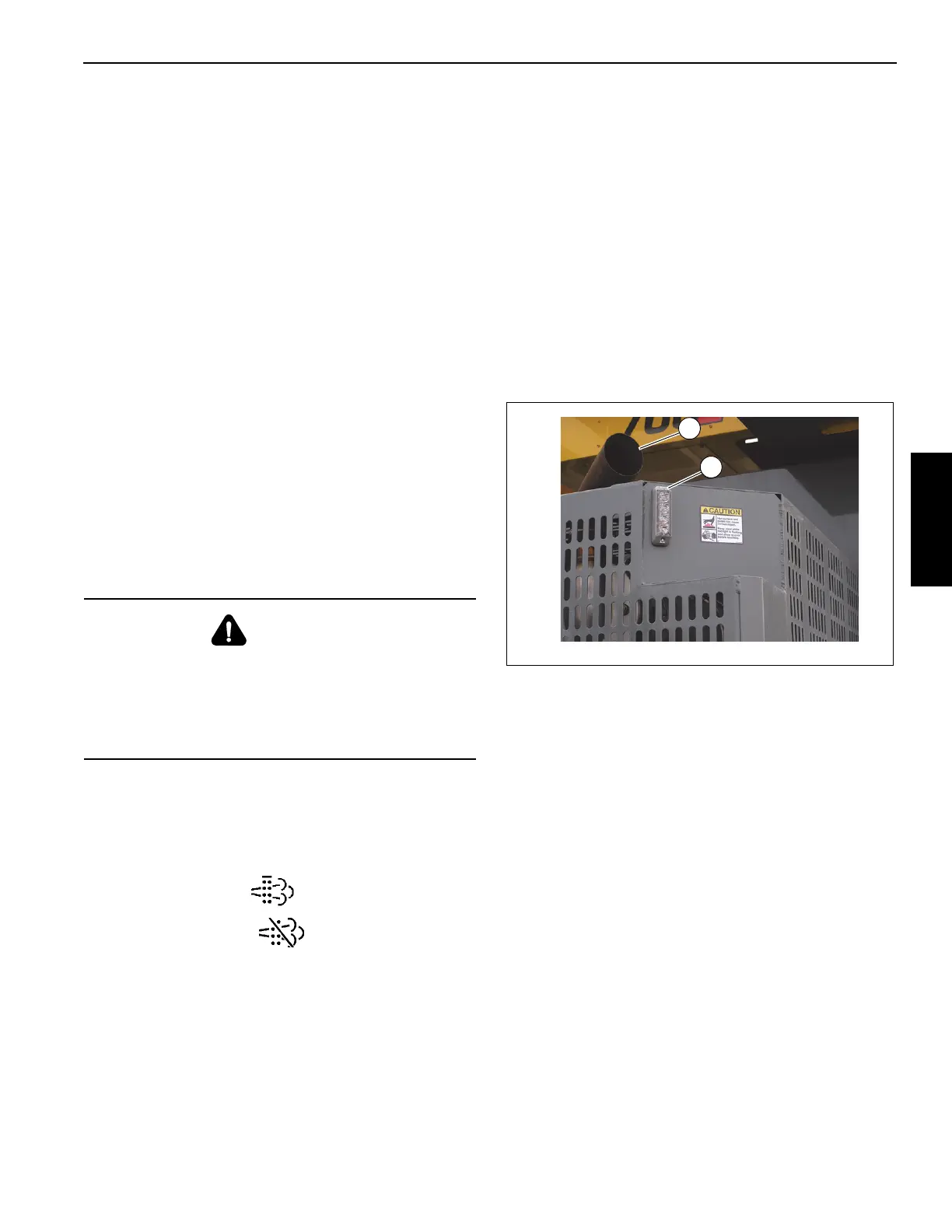
Set up a safe area around the crane’s exhaust; remove tools,
rags, grease or any debris from the engine exhaust area. As
a warning, the light (1, Figure 3-5) below the exhaust pipe (2,
Figure 3-5) will flash during regeneration.
With the engine idling push the EXHAUST System Cleaning
Switch (9) to initiate regeneration.
Within 5 seconds the engine should rev up to 1000 to 1400
rpm. The engine will continue to run at this speed for up to 45
minutes.
Pressing the brake or throttle pedal during regeneration or
activating the Inhibit Regen Switch will interrupt the
regeneration process.
Make sure the crane and surrounding area are monitored
during manual regeneration. If any unsafe condition occurs,
shut off the engine immediately.
During this period the sound of the engine may change.
When regeneration is complete the engine will return to its
normal idle speed.
Boom Section 1/Section 2 Selector Switch
and Indicator
The Boom Section 1/Section 2 Selector Switch (10)
(Figure 3-4) and Indicator (11) are located on the overhead
control panel. The switch (10) is a three position rocker type
switch that is used in conjunction with the Boom Manual/
Automatic Mode Selector Switch (12).
When the Boom Manual/Automatic Mode Selector Switch
(12) is positioned to manual mode, the Boom Section 1/
Section 2 Selector Switch (10) is used to select the
section(s) of the boom that will telescope in and out when
actuated. When the switch (10) is position to Section 2 (top
of switch is pressed), sections 2, 3, and 4 can be extended
and retracted; when the switch is positioned to Section 1
(bottom of switch is pressed), section 1 can be extended and
retracted. When not operating in the manual mode, the
Boom Section 1/Section 2 Selector Switch (10) should be in
the OFF (center) position.
When operating in the manual mode, the Boom Section 1/
Section 2 Indicator (11) (Figure 3-4) will indicate which boom
section has been activated by the Boom Section 1/Section 2
Selector Switch (10).
WARNING
Fire or Burn Hazard!
During the regeneration process the exhaust becomes
very hot. Do not park the vehicle near flammable objects.
Use caution near the exhaust tailpipe during regeneration
as it will become very hot.