Section 6Electrical System
6-4
Initial Start-Up Or Start-Up After
Automatic Shut-Off (cont.)
2. REFRIGERATION SYSTEM
START-UP
The compressor starts after the 45-second
water purge, and it remains on throughout
the Freeze and Harvest cycles.
The hot gas valve(s) remains on for the
first 5 seconds of the initial compressor
start-up.
At the same time the compressor starts,
the condenser fan motor (air-cooled
models) is supplied with power. It
continues to be supplied with power
throughout the Freeze and Harvest cycles.
The fan motor is wired through a fan
cycle pressure control, and may cycle on
and off. (The compressor and the
condenser fan motor are wired through
the contactor. Any time the contactor coil
is energized, these components are
supplied with power.)
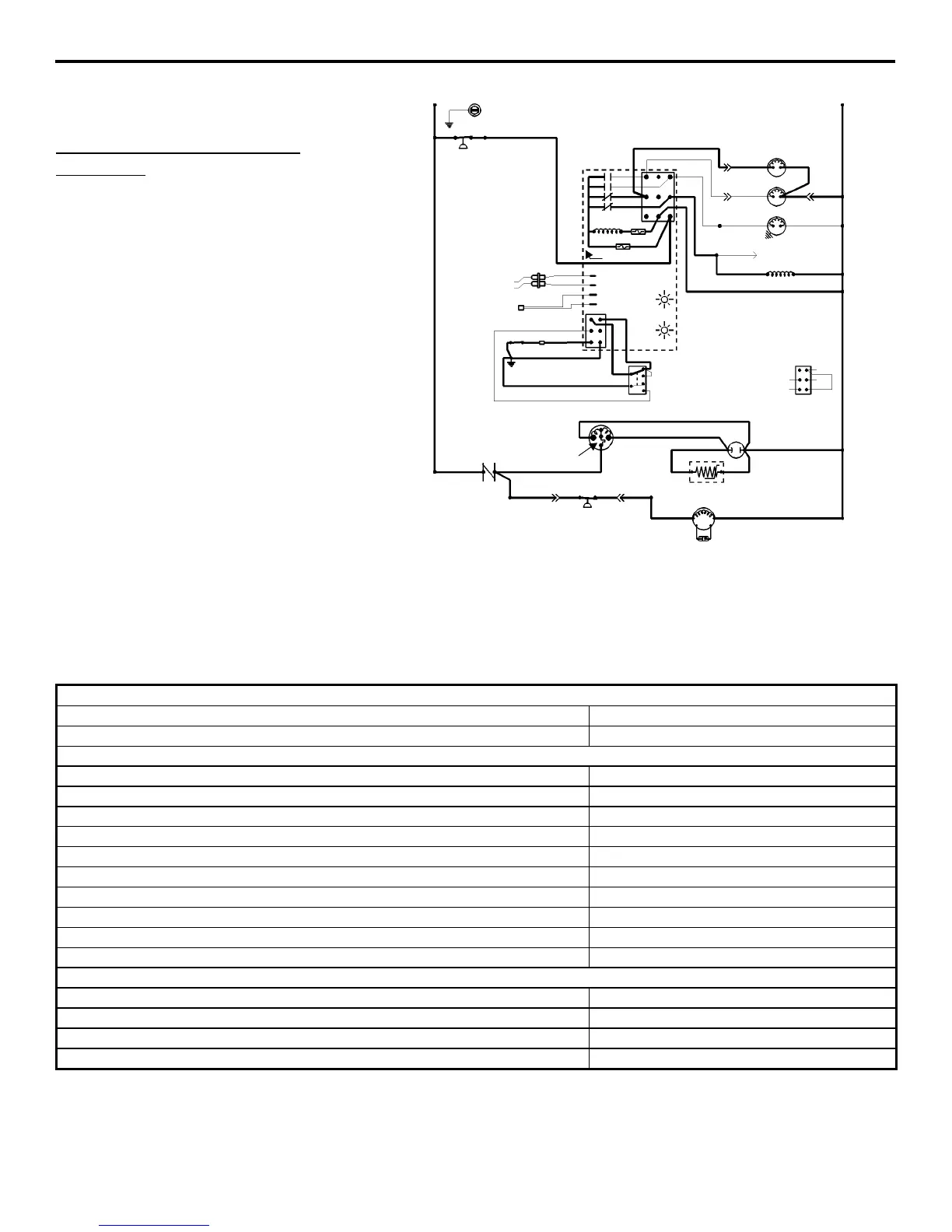
(Old Style Control Board Shown)
Self-Contained Models
2. Refrigeration System Start-Up (5 Seconds)
Toggle Switch
ICE
Bin Switch
Closed
Control Board Relays
#1 Open
Water Pump OFF
#2 Closed
Hot Gas Solenoid ON
#3 Open
Water Dump Valve OFF
#4 Closed
Contactor Coil ON
Compressor ON
Condenser Fan Motor ON
Safety Controls (Which could stop ice machine operation)
High Pressure Cut-Out Closed
Main Fuse (On Control Board) Closed
Transformer Fuse (On Control Board) Closed
Thermistor Operation OK
V1
L1
TB35
TB30
TB30
TB30
TB30
SEE SERIAL PLATE FOR VOLTAGE
L2
N
TB32
55
61
60
77
80
76
75
98
99
TB3
TB37
59
73
74
56
58
57
HOT GAS
SOLENOID
DUMP
SOLENOID
WATER
PUMP
TERMINATES AT
PIN CONNECTION
CONTACTOR COIL
TRANS. FUSE
FUSE
7A
ICE THICKNESS PROBE
DISCHARGE LINE THERMISTOR
3
1
2
4
1D
1C
1B
1
BIN SWITCH
62
63
65
64
66
66
67
62
69
68
HARVEST LIGHT/
SAFETY CODE LIMIT LIGHT
BIN SWITCH LIGHT
ICE
OFF
CLEAN
TOGGLE SWITCH
VIEW FOR WIRING
62
66
69
67
68
HIGH
PRESSURE
CUTOUT
←
←←
←INTERNAL
WORKING VIE
TB35
TB33 TB34
TB30
TB30
49
47
COMPRESSOR RUN CAPACITOR
SR
C
RR
*OVERLOAD
PTCR
46
45
50
42
48
52
85
86
53
FAN CYCLE
CONTROL
L1
RUN CAPACITOR**
FAN MOTOR
(AIR-COOLED ONLY)
CONTACTOR
CONTACTS