Section 6Electrical System
6-46
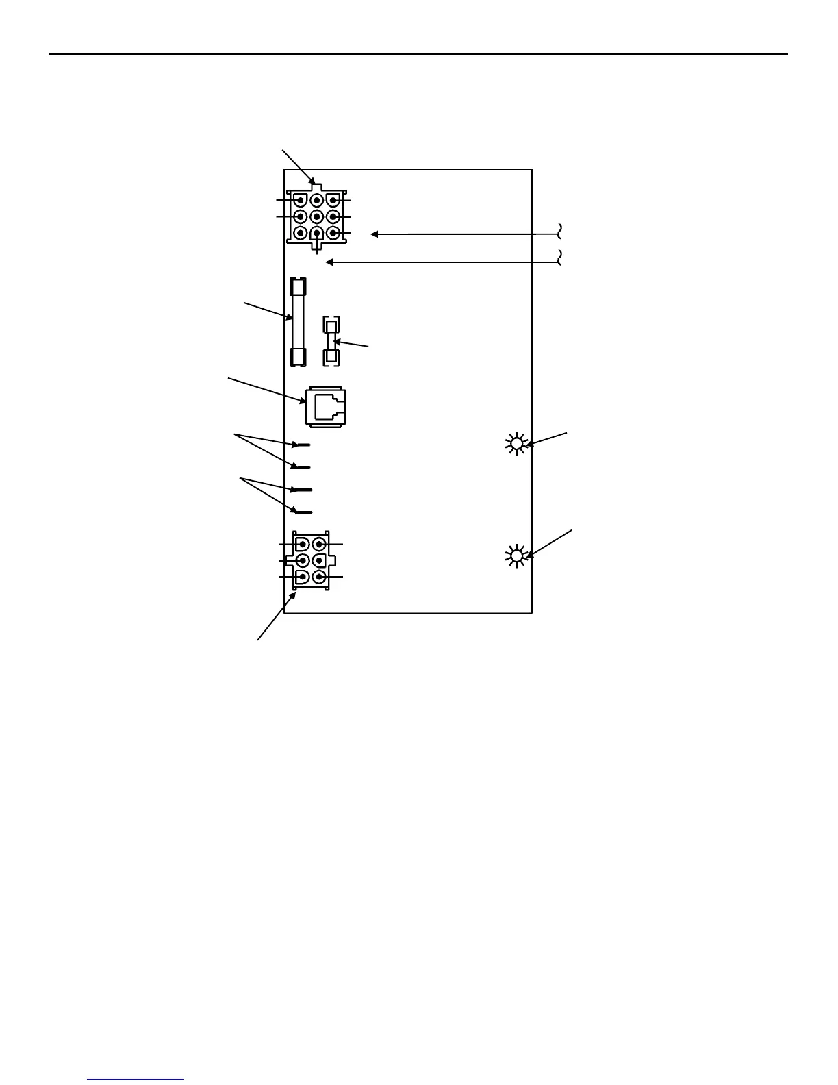
ELECTRONIC CONTROL BOARD (OLD STYLE)
Old Style Control Board
General
The control board controls all electrical components,
including the ice machine sequence of operation.
Prior to diagnosing, you must understand how the
control board functions, and what it is supposed to
do.
Refer to wiring diagrams and ice machine sequence
of operation sections for details, including:
• Initial Start-Up or
Start-Up After Automatic Shut-Off
• Freeze Sequence
• Harvest Sequence
• Automatic Shut-Off
• Self-Cleaning
Refer to pages 6-48 and 6-49 for additional control
board information.
57
55
58
68
65
60
61
56
1D
1C
1B
1
67
63
62
MAIN FUSE (7A)
AUTOMATIC CLEANING SYSTEM
(AuCS)
ACCESSORY PLUG
ICE THICKNESS PROBE
(3/16” CONNECTION)
DISCHARGE LINE THERMISTOR
(1/4” CONNECTION)
DC LOW VOLTAGE
ELECTRICAL PLUG
NUMBERS MARKED ON WIRES
HARVEST LIGHT/
BIN SWITCH LIGHT
TRANSFORMER FUSE
(.125A - 60HZ)
-
AC LINE VOLTAGE
ELECTRICAL PLUG
NUMBERS MARKED ON WIRES
N 115V
L
2
208-230V
L
1
PRIMARY
POWER SUPPLY
SV1542