Section 6Electrical System
6-6
Freeze Sequence (cont.)
4. FREEZE
The water pump starts after the 30-second
pre-chill. An even flow of water is
directed across the evaporator and into
each cube cell, where it freezes.
When sufficient ice has formed, the water
flow (not the ice) contacts the ice
thickness probes. After approximately 7
seconds of continual contact, a harvest
cycle is initiated.
NOTE: The ice machine cannot initiate a
harvest cycle until a 6-minute freeze lock
has expired.
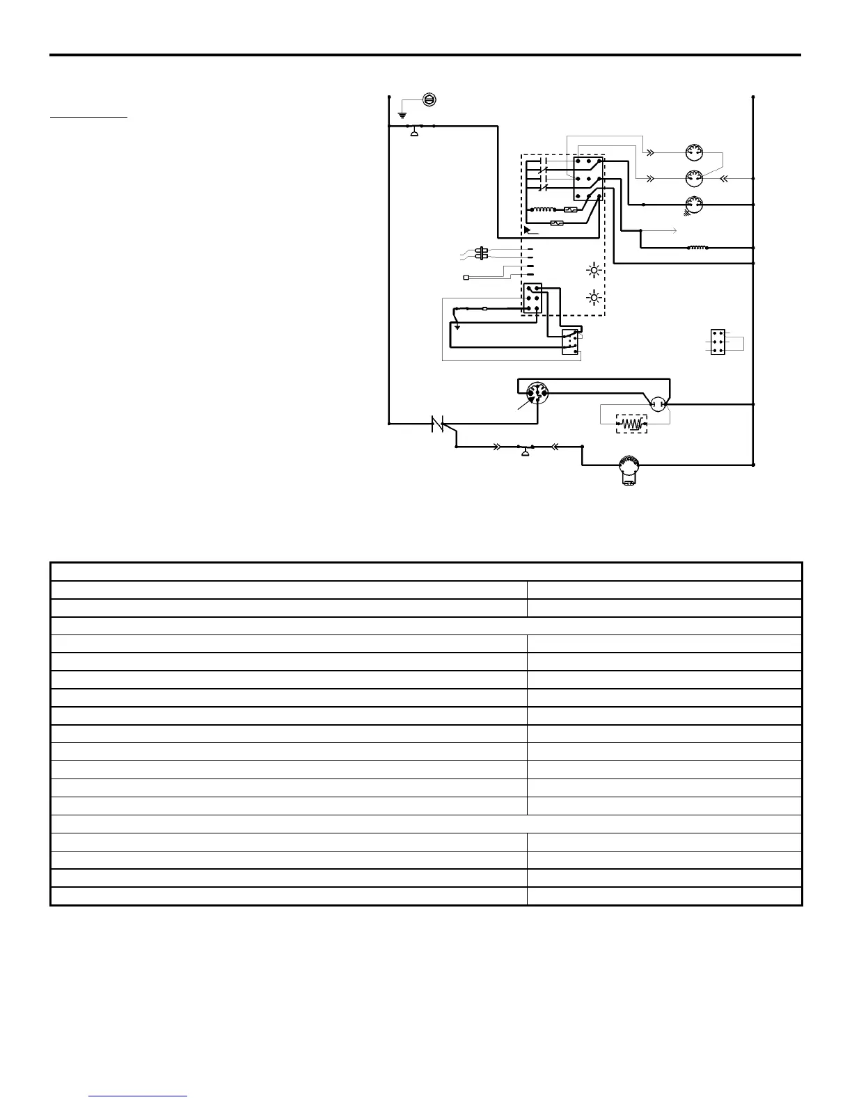
(Old Style Control Board Shown)
Self-Contained Models
4. Freeze (Until 7 Seconds of Water Contact with Ice Thickness Probe)
Toggle Switch
ICE
Bin Switch
Closed
Control Board Relays
#1 Closed
Water Pump ON
#2 Open
Hot Gas Solenoid OFF
#3 Open
Water Dump Valve OFF
#4 Closed
Contactor Coil ON
Compressor ON
Condenser Fan Motor ON
Safety Controls (Which could stop ice machine operation)
High Pressure Cut-Out Closed
Main Fuse (On Control Board) Closed
Transformer Fuse (On Control Board) Closed
Thermistor Operation OK
SV1562
L1
TB35
TB30
TB30
TB30
TB30
SEE SERIAL PLATE FOR VOLTAGE
L2
N
TB32
55
61
60
77
80
76
75
98
99
TB3
TB37
59
73
74
56
58
57
HOT GAS
SOLENOID
DUMP
SOLENOID
WATER
PUMP
TERMINATES AT
PIN CONNECTION
CONTACTOR COIL
TRANS. FUSE
FUSE
7A
ICE THICKNESS PROBE
DISCHARGE LINE THERMISTOR
3
1
2
4
1D
1C
1B
1
BIN SWITCH
62
63
65
64
66
66
67
62
69
68
HARVEST LIGHT/
SAFETY CODE LIMIT LIGHT
BIN SWITCH LIGHT
ICE
OFF
CLEAN
TOGGLE SWITCH
VIEW FOR WIRING
62
66
69
67
68
HIGH
PRESSURE
CUTOUT
←
←←
←INTERNAL
WORKING VIE
TB35
TB33 TB34
TB30
TB30
49
47
COMPRESSOR RUN CAPACITOR
SR
C
RR
*OVERLOAD
PTCR
46
45
50
42
48
52
85
86
53
FAN CYCLE
CONTROL
L1
RUN CAPACITOR**
FAN MOTOR
(AIR-COOLED ONLY)
CONTACTOR
CONTACTS