Section 6 Electrical System
6-11
Initial Start-Up Or Start-Up After
Automatic Shut-Off (cont.)
2. REFRIGERATION SYSTEM
START-UP
The compressor, remote condenser fan
motor and liquid line solenoid valve
energize after the 45-second water purge,
and remain on throughout the Freeze and
Harvest cycles.
The hot gas valve and harvest pressure
regulating (HPR) solenoid valve remain
on for the first 5 seconds of the initial
compressor start-up.
(The compressor and the condenser fan
motor are wired through the contactor.
Any time the contactor coil is energized,
these components are supplied with
power.)
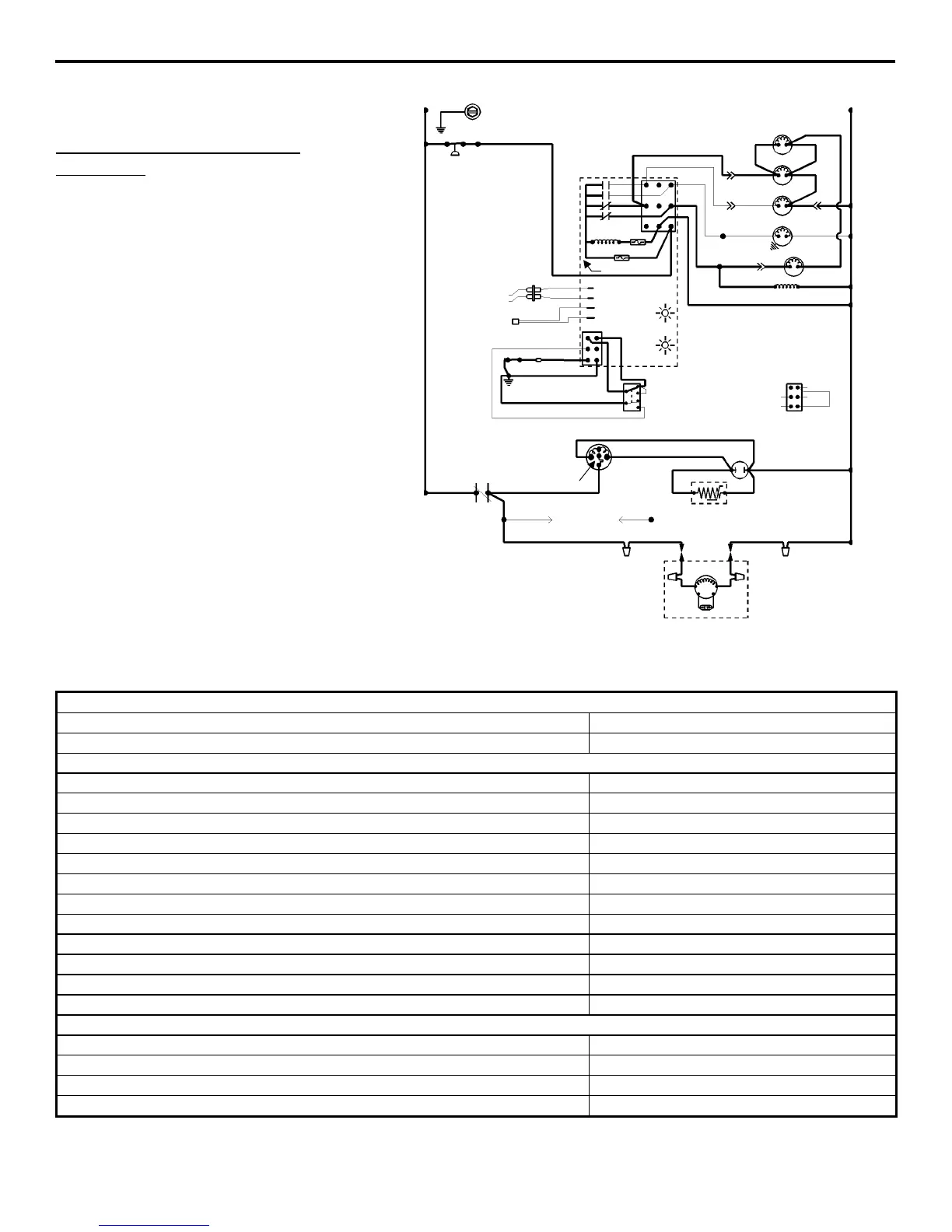
(Old Style Control Board Shown)
Remote Models
2. Refrigeration System Start-Up (5 Seconds)
Toggle Switch
ICE
Bin Switch
Closed
Control Board Relays
#1 Open
Water Pump OFF
#2 Closed
Hot Gas Solenoid ON
Harvest Pressure Regulating (HPR) Solenoid ON
#3 Open
Water Dump Valve OFF
#4 Closed
Contactor Coil ON
Liquid Line Solenoid Energized
Compressor ON
Condenser Fan Motor ON
Safety Controls (Which could stop ice machine operation)
High Pressure Cut-Out Closed
Main Fuse (On Control Board) Closed
Transformer Fuse (On Control Board) Closed
Thermistor Operation OK
SV1553
(74)
L1
TB35
SEE SERIAL PLATE FOR VOLTAGE
L2 (N)
TB32 (55)
HIGH
PRESSURE
CUT-OUT
HPR
SOLENOID
(79)(78)
(61)
(60)
(71)
(76)
(80)
HOT GAS
SOLENOID
DUMP
SOLENOID
TB30
TB30
TB30
TB30
(75)
(98) (99)
WATER
PUMP
TB31
TB37
(57)
(58)
(59) (82)(83)
LIQUID LINE
SOLENOID
CONTACTOR
COIL
(56)
(73)
(81)
TRANS. FUSE
FUSE (7A)
3
1
2
4
ICE THICKNESS PROBE
DISCHARGE LINE THERMISTOR
1D
1
1C
1B
LOW D.C.
VOLTAGE
PLUG
(62)
(63)
(65)(64)
(66)
BIN SWITCH
(66)
(67)
(62)
(69)
(68)
ICE
OFF
CLEAN
HARVEST LIGHT/
SAFETY LIMIT CODE LIGHT
BIN SWITCH LIGHT
TOGGLE SWITCH
←
←←
←INTERNAL
WORKING VIEW
66
62
67
68
69
VIEW FOR WIRING
(49)
(47)
(46)
(45)
(50)
TB30
TB30
TB35
(48)(42)
(51)
(52)
L1
TB33 TB34
(53)
(F1) (F2)
CONTACTOR
CONTACTS
TERMINATES AT
PIN CONNECTION
COMPRESSOR RUN CAPACITOR
RR
PTCR
REMOTE FAN
MOTOR
RUN CAPACITOR
REMOTE
CONDENSER
*OVERLOAD
RS
C
 Loading...