Manitowoc Published 12-10-19, Control # 258-05 4-93
MLC90A-1/MLC100-1 OPERATOR MANUAL SETUP AND INSTALLATION
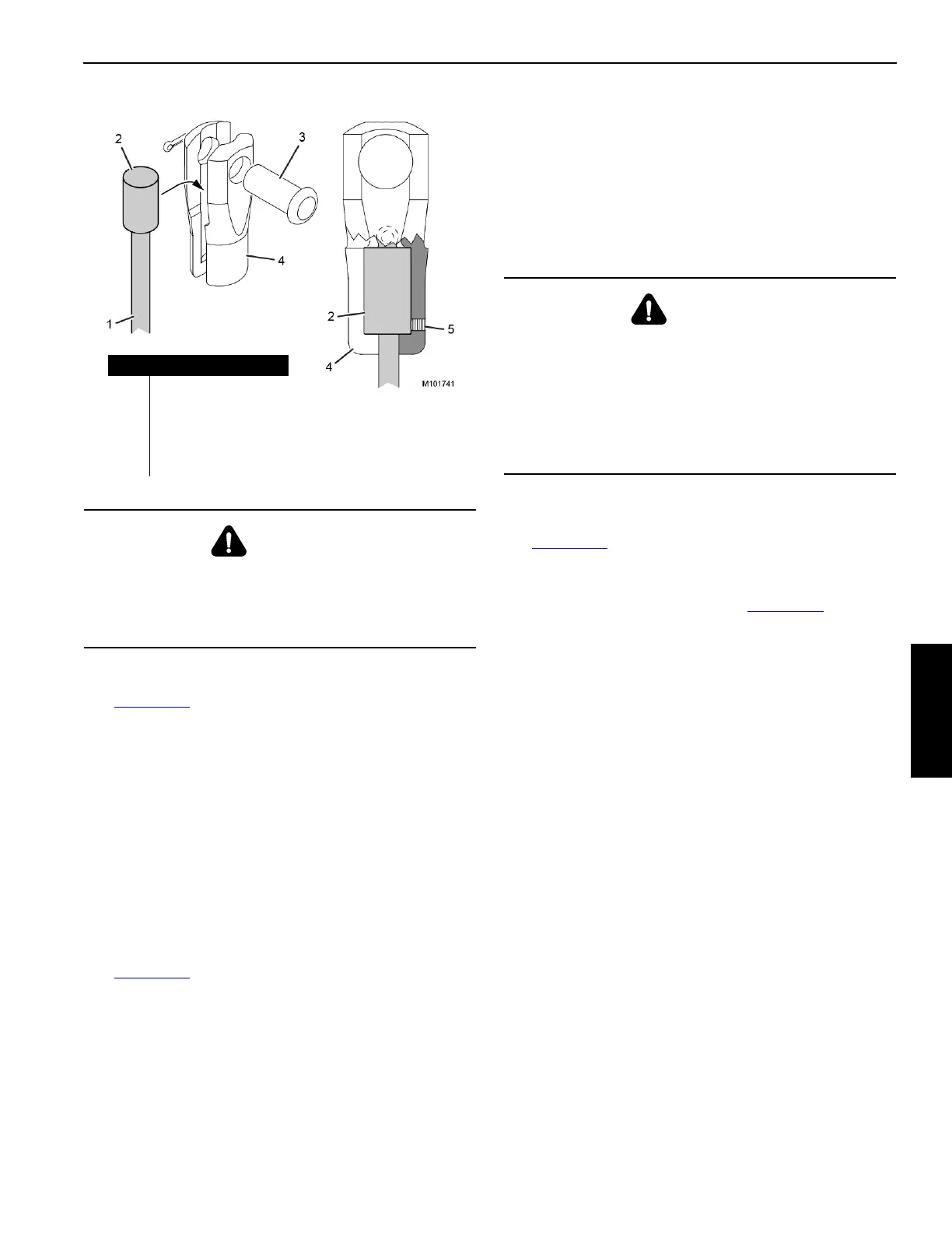
Anchoring Wire Rope to Button Socket
See Figure 4-60
1. Remove the pin (3) from the button socket (4).
2. Loosen the locking screw (5) so it is not protruding past
the inner surface of the button socket.
3. Install the button (2) end of the load line (1) into the
button socket (4). Make sure the button socket is fully
seated in the button.
4. Securely tighten the locking screw (5). There is no hole
or flat spot on the button for the locking screw.
5. Pin the socket to the anchor point.
Pad Eye Usage for Wire Rope Reeving
See Figure 4-59
General
Some rotation-resistant wire rope supplied by Manitowoc is
equipped with a pad eye welded to the leading end of the
wire rope or to the button on the end of the wire rope.
A rigging line can be attached to the pad eye to make it
easier to reeve the load block.
Safety
1. Do not exceed the approximate capacities listed in
Figure 4-59
.
2. Make sure the rigging line and the attaching hardware
(clips and rope connectors) are rated for the
approximate capacities shown in Figure 4-59
.
3. Inspect the pad eye prior to each use. Replace it if:
• Any original dimensions have changed
• Cracks or breaks exist in the metal or the weld
Breaking in Wire Rope
After installing a new wire rope, break it in by operating it
several times under light load at reduced speed. This
practice allows the wire rope to form its natural lay and the
strands to seat properly.
NOTE The wire rope will stretch during the break-in period,
reducing the wire rope’s diameter as the strands
compact around the core.
The dead wraps of wire rope on the drum can become slack
during operation, even if the utmost care is used during
installation of the wire rope. This slackening is caused by the
normal stretch that occurs in a new wire rope under tension
and periodically throughout the wire rope’s life from release
of the load.
When slackness is noted, tightly wind the dead wraps of wire
rope onto the drum. If left uncorrected, a wedging action with
subsequent layers will occur, and the resultant abrasion may
cause broken wires in the dead wraps.
WARNING
Falling Load Hazard!
The wire rope must be installed in the button socket as
instructed below. Failing to follow these instructions can
result in wire rope damage or failure.
Figure 4-60
Item Description
1 Load Line
2Button
3Pin
4 Button Socket
5 Locking Screw
WARNING
Flying Part Hazard!
Pad eye on end of wire rope has been provided for
reeving purposes only. Any other use is neither
intended nor approved.
The pad eye can break and fly apart with considerable
force if it is overloaded, not used properly, or not
maintained properly.