Manitowoc Published 12-10-19, Control # 258-05 4-45
MLC90A-1/MLC100-1 OPERATOR MANUAL SETUP AND INSTALLATION
Install Load Lines
1. Route the load lines up the boom (and jib, if equipped)
and over the desired guide sheaves in the boom top
(and jib top, if equipped). See Figure 4-27
and the Load
Line Reeving Diagrams at the end of this section.
2. Install the load block(s) and the hook-and-weight ball(s)
(Figure 4-27
) after the boom (and jib, if equipped) is
raised to a convenient height. See "Boom Raising
Procedure" on page 4-60.
3. Be sure to route the load lines through the block-up limit
weights. See Install Boom Block-Up Limit Components
on page 4-39.
4. Read the following topics:
• "Wire Rope Installation" on page 4-86
• "Load Line Reeving" on page 4-95.
• The Wire Rope Specifications chart located in the
Capacity Chart Manual supplied with the crane for:
- Parts of the line required for various loads
- Wire rope lengths and notes about the hoisting
distance for various parts of the line
- Maximum spooling capacity of the load drums
• Load Line Reeving diagrams at the end of this
section.
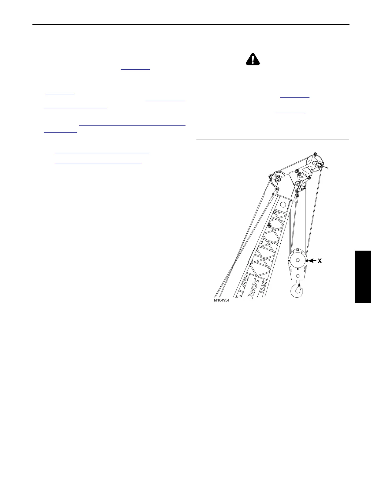
WARNING
Falling Load Hazard!
For some parts of line, it is necessary to reeve the load
line over the upper boom point to the load block hanging
from the lower boom point (see Figure 4-28
).
For these cases, REMOVE the front rope guard bar from
the load block (location X in Figure 4-28
) to prevent the
load line from rubbing against the bar.
Failing to perform this step can result in wire rope damage
and possible failure.