OPERATING CONTROLS AND PROCEDURES MLC90A-1/MLC100-1 OPERATOR MANUAL
3-50
Published 12-10-19, Control # 258-05
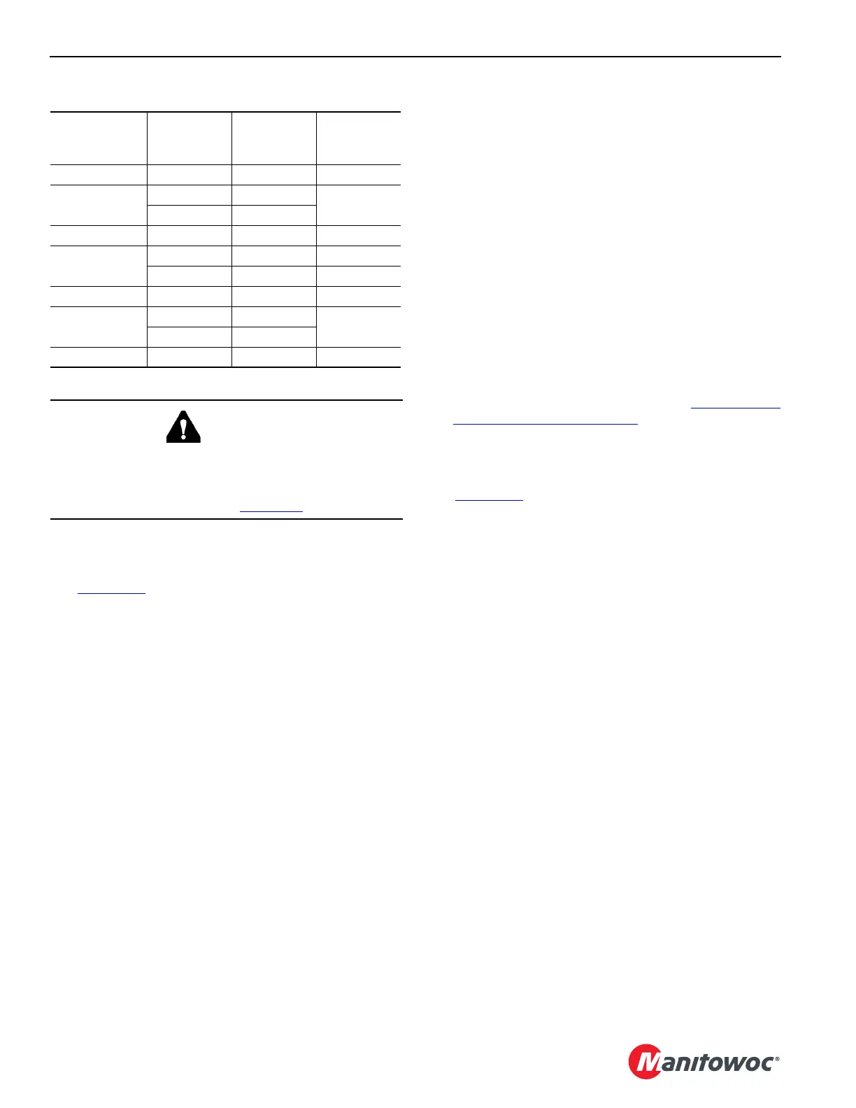
Table 3-13. Maximum Cantilevered Boom Inserts
Preparing Cantilevered Boom Inserts for
Low Clearance Travel
See Figure 3-19.
1. The following instructions assume:
a. The equalizer (4, View A) is anchored to the boom
butt with tie-back links (3).
b. The required length of inserts (2, View B) is properly
assembled, pinned to the boom butt, and resting on
blocking at least 457 mm (18 in) high.
See Section 4 of the Operator Manual for detailed
assembly instructions.
c. The boom pendants are removed.
2. Using the gantry cylinders switch on the right console,
fully retract the gantry cylinders (7, View B) to lower the
gantry (5, View C).
To activate the gantry cylinders switch, the Boom Butt
Configuration must be selected in the RCL/RCI Display.
3. Slowly pay out the boom hoist wire rope as required
while the gantry lowers.
4. Remove the safety pin (8, View D), the collar (9), and the
pin (10) from both counterweight handling links (11).
5. Rotate the counterweight handling links (11, View D)
toward the counterweight and align the holes in the
counterweight handling links with those in the tie-down
links (12).
6. Install the pins (10, View D), the collars (9), and the
safety pins (8) to attach the counterweight handling links
(11) to the tie-down links (12).
The pin heads must face inward.
7. Using the gantry cylinders switch on the right console,
extend the gantry cylinders until the counterweight
handling links (11, View E and F) and the tie-down links
(12) are taut.
8. Make sure the boom hoist wire rope is spooled properly
on the boom hoist drum.
9. Raise the boom inserts to no higher than 2° above
horizontal.
10. The crane is now ready for travel. See Low Clearance
Travel Limitations on page 3-46.
Returning Gantry to Normal Operating
Position
See Figure 3-19.
1. Lower the boom inserts onto blocking (6, View B) at
least 457 mm (18 in) high.
2. Using the gantry cylinders switch on the right console,
fully retract the gantry cylinders (7, View C and D) to
lower the gantry (5).
3. Slowly pay out the boom hoist wire rope as required
while the gantry lowers.
4. Support the counterweight handling links (11, View D)
and remove the safety pins (8), the collars (9), and the
pins (10).
5. Rotate the counterweight handling links (11, View D) to
vertical and reconnect the pins (10), the collars (9), and
the safety pins (8) to the counterweight handling links.
6. Makes sure the boom hoist wire rope is spooled properly
on the boom hoist drum.
7. Using the gantry cylinders switch on the right console,
fully extend the gantry cylinders (7, View B) to raise the
gantry (5) to the normal operating position.
8. Complete boom assembly as instructed in Section 4 of
the Operator Manual.
9. Select the desired Boom Configuration in the RCL/RCI
Display.
10. Raise the boom to the desired operating angle.
Length
3 m
(9.8 ft)
Insert
6 m
(19.7 ft)
Insert
12 m
(39.4 ft)
Insert
3 m (9.8 ft) 1 0 0
6 m (19.7 ft)
01
0
20
9 m (29.5 ft) 1 1 0
12 m (39.4 ft)
001
210
15 m (49.2 ft) 1 0 1
18 m (59.1 ft)
01
1
20
21 m (69.9 ft) 1 1 1
WARNING
Structural Damage Hazard
To avoid damage and possible collapse of boom, do not
attempt low clearance travel with cantilevered boom
inserts longer than specified in Table 3-13