CONTROLS AND OPERATING PROCEDURES OPERATOR MANUAL NTC55
3-16 Published 9-26-2018 Control # 646-02
Hoist Rotation Indicators (HRI)
The Hoist Rotation Indicators for the auxiliary and main hoist
is located on top of each hoist control lever. Each indicator is
electronically driven by an input signal from a sensor
attached to its related hoist and an output signal from a
control module. Each hoist control lever pulses when its hoist
is running so the operator’s thumb can sense it.
The hoist drum rotation indicator (DRI) and last layer
indicator (LLI) are integrated into one monitoring system
located on the left side of the hoist.
Last Layer Indicator (LLI)
The last layer indicator (LLI) is programmed to notify the
operator when the last usable layer of rope on the hoist drum
(main or auxiliary) is reached. The buzzer will sound and the
icon on the console display panel will flash.
Minimum Wrap Indicator
The minimum wrap indicator is programmed to notify the
operator when there are three wraps of wire or (optional)
synthetic rope left on the hoist drum. When the minimum
wrap of the last layer is reached, the icon on the console
display panel will show solid. This feature does not lock out
the hoist down function. Both main and auxiliary hoists use
this indicator.
Single Axis Controller (Boom Lift/Hoist
Cable)
The boom lift control level (35, Figure 3-5) and the main hoist
control lever (36, Figure 3-5) are located on the right
armrest.
Push the boom lift lever (35) forward to lower the boom, pull
back to raise the boom.
Push the main hoist lever (36) forward to play out loadline,
pull the lever back to take up loadline.
Single Axis Controller (Swing/Boom Tele)
The swing control lever (38, Figure 3-5) and the telescope or
auxiliary hoist control lever (37, Figure 3-5) are located on
the left armrest.
Push the swing lever (38) forward to rotate the
superstructure clockwise, pull the swing lever back to rotate
the superstructure counterclockwise.
Push the telescope lever (37) forward to extend the boom,
pull the lever back to retract the boom. If equipped with an
auxiliary hoist, this lever (37) operates the auxiliary hoist
lever and the telescope pedal (3, Figure 3-4) controls the
boom telescoping function.
Cab Tilt Switch
The cab tilt switch button (41, Figure 3-5) is located on the
right seat armrest. It is a three position, momentary spring
centered to off rocker switch. It has two positions, Up and
Down, allowing the cab to be tilted either up or down.
NOTE: The cab tilt feature and the cab must be completely
down before travel.
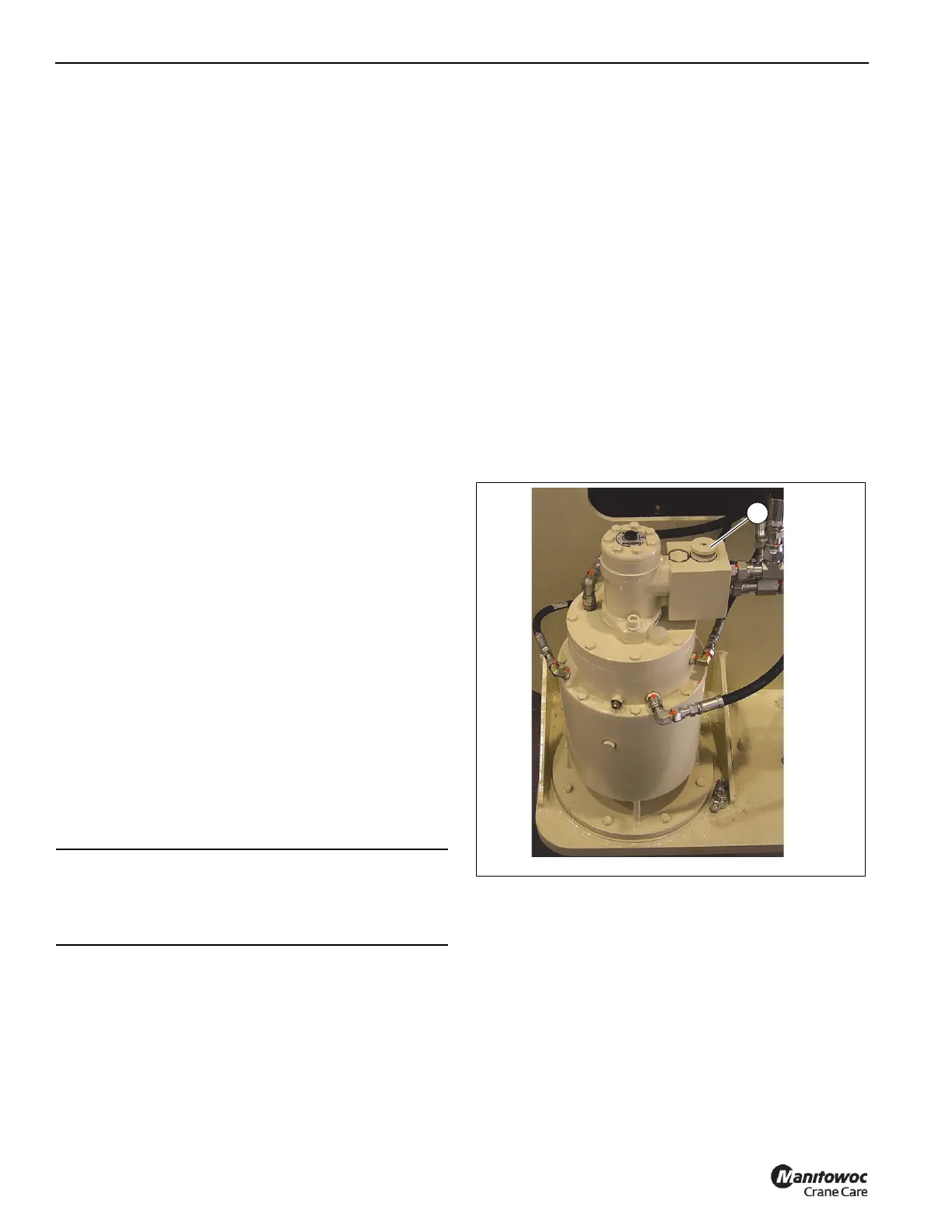
Adjustable Swing Speed Valve
The crane is equipped with an adjustable swing speed valve
(1, Figure 3-7) that sets the maximum swing speed of the
machine. Turn the valve knob clockwise to increase and
counterclockwise to decrease speed.
HEATER
The diesel powered supplemental heater (1, Figure 3-8) is
located under the cab support frame and supplies heat to the
crane cab. The heater controls the temperature of the crane
cab by cycling coolant between the heater and the climate
control unit located under the cab seat. Controls (25, 26, 27,
Figure 3-4) for the heater are located on the overhead
control panel in the crane cab.
CAUTION
Do not actuate the Swing Control Lever while the Swing
Brake is engaged, as the turret may push through the
brake. Damage to the swing brake can occur.