7Contact us at www.mantis.com
LET’S BEGIN
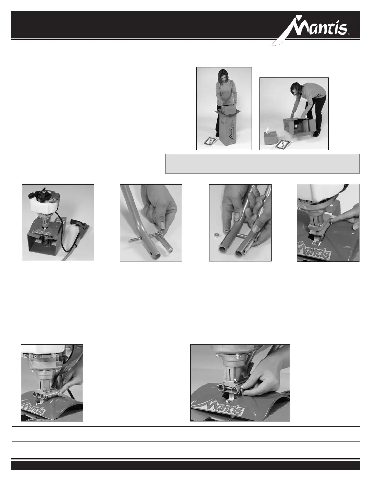
• With the box upright, open the box and remove the
tine box and the loose parts at the top of the tiller
box. Do not remove any other parts from the box.
• Lay the box on one side and open the bottom aps.
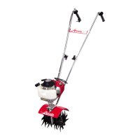
• Return the box to an upright position (as shown in
Figure A) and pull the box straight up.
• Leave the engine and throttle handle in the cradle to
assist in the assembly.
• Lay everything out so you can easily identify the
parts (see parts image and list on page 6).
Assembly
• Slide the lower handles that
you’ve just put together into
the two recessed channels.
• Make sure you insert them
from the rear of the tiller
(gasoline tank faces away
from the operator) so the
bolt ts along the back of
the housing.
• Slide the second 3-inch
bolt (T11) through the
second set of holes in
the short legs. Add a
lock
nut (T14)
and tighten
nger tight until you’ve
completed assembly.
LOWER HANDLE ASSEMBLY
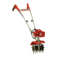
• For ease of assembly and
stability, it is important that you
keep the engine assembly in its
cardboard cradle.
1
6
• Lay all handle parts within easy
reach. You’ll need one of the
handle clamps (T7) and one of
the lower handles (T3). Note that
the lower handles have a short
leg on one end.
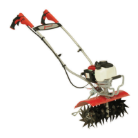
• Fit the handle clamp along
the outside of the short leg as
shown. Line up the holes on the
clamp and the leg.
2
• Choose one of the two 3-inch bolts
(T11). Slide it through the rst set
of holes near the elbow where the
lower handle curves. (Pictures 2 & 3)
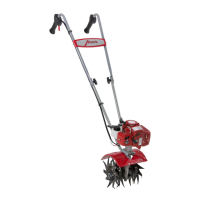
• Now slide the other lower handle
onto the 3-inch bolt. Fit the other
clamp onto the other handle’s
short leg. Add a lock nut (T14) and
tighten “nger tight” (as tight as you
can make them without the use of a
tool). (Picture 3)
3
• Locate recessed channels
below the engine.
4
5
NOTE: THE LOCK NUTS ARE STAMPED. FINGER TIGHT IS APPROXIMATELY 1/2 TO 1-1/2 TURNS UNTIL YOU’VE COMPLETED ASSEMBLY.
See page 6 to identify part numbers.
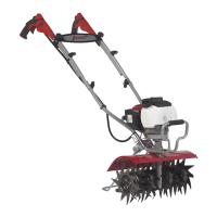
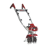
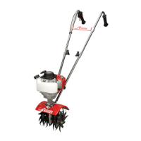
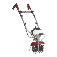
NOTE: Some of the photos in this manual do not represent your
tiller engine. They are for assembly purposes only.
Figure A
Figure B