8 Operator’s Manual
Assembly (Continued)
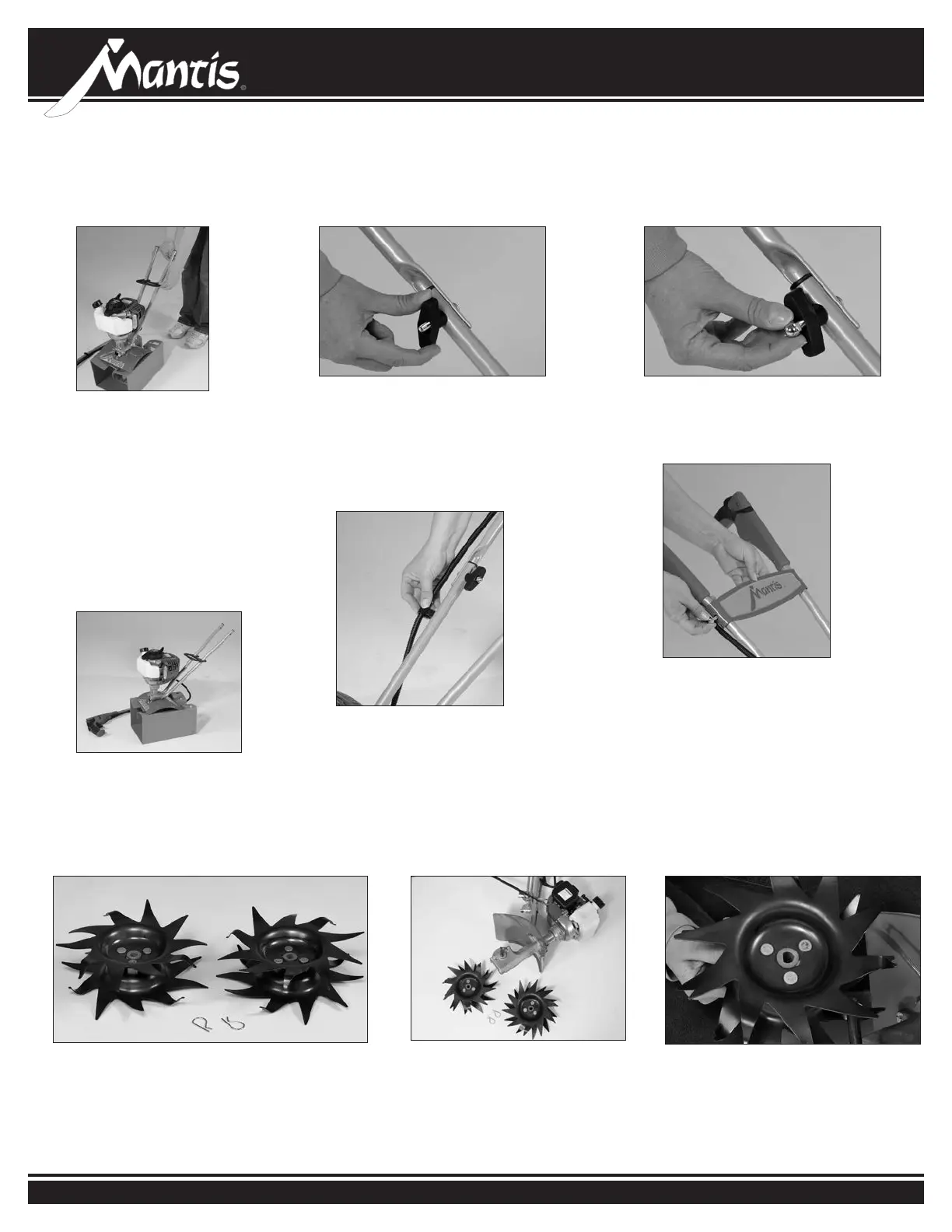
UPPER HANDLE ASSEMBLY
• Lightly squeeze the lower
handles (T3) toward one another
so they line up with the two
smaller holes on the carrying
handle (T10). Then slide the
carrying handle over and down
the lower handles. It will rest
about four to six inches above the
fender.
• Gently pull the lower handles out
to their original position.
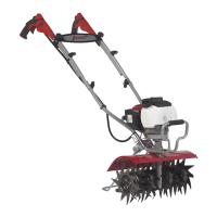
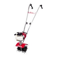
• Your Mantis tiller will look like
this when the lower handle
assembly is complete.
7a
7b
• You will need the two tines and two retaining
pins.
• Remove the unit from the
cardboard cradle and lay the
unit on its side.
• You will notice that one side of the
tine has a circular hole, while the
other has a D-shaped hole.
TINE ASSEMBLY
1 2 3
8
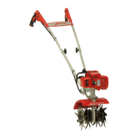
• Lift the upper handle until the holes
line up with the lower handle.
•
Insert carriage bolt (T42) from outside in.
• Screw on knob (T12) and fully tighten
the knob at the pivot point.
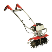
• Repeat steps 8 and 9 to install the
other upper handle onto the other
lower handle.
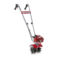
• Use throttle clip (T9) to secure the
throttle cable and wire in place on the
lower handle.
10
9
• Cap the exposed bolt with an acorn
nut (T13) and tighten with your 7/16”
wrench until snug. Do not over tighten.
• Line it up holes on handle brace (T4)
with the holes on the upper handles.
Insert a cap screw (T15) and a lock nut
(T14) on either side.
• Use a wrench to tighten cap screws
and lock nuts.
• Use wrench to tighten all nuts and
bolts rmly and securely.
11