LEFT
n lTTI
]1-' III I
]'1fll! rl
1 J 111 J ·1]
r1l1T j
--::....-:-~.
SPEAKER SYSTEM 1
+
--c
- -
SPEAKER SYSTEMS·
. SYSTEM 1
~~R~~L~~
ltjldJ ldJ ldJ
SYSTEM 2
~~l6JlaJ[BJffi
- -
+
SPEAKER SYSTEM 2
RIGHT
r TTJ n
IIU· r~I··~
r -I!] I1I:r
ILLllrili ~
LIT ITIH
---
.~._--::---_~.
FM QUADRADIAL OUTPUT JACK
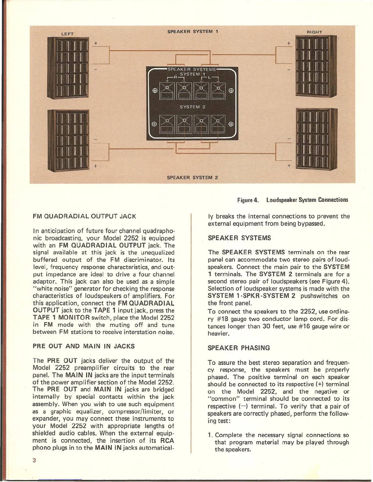
Figure 4. Loudspeaker System Connections
Iy breaks the internal connections to prevent the
external equipment from being bypassed.
In anticipation of future four channel quadrapho-
nic broadcasting, your Model 2252 is equipped
with an FM QUADRADIAL OUTPUT jack. The
signal available at this jack is the unequalized
buffered output of the FM discriminator. Its
level, frequency response characteristics, and out-
put impedance are ideal to drive a four channel
adaptor. This jack can also be used as a simple
"white noise" generator for checking the response
characteristics of loudspeakers of amplifiers. For
this application, connect the FM QUADRADIAL
OUTPUT jack to the TAPE 1 input jack, pressthe
TAPE 1 MONITOR switch, place the Model 2252
in FM mode with the muting off and tune
between FM stations to receive interstation noise.
PRE OUT AND MAIN IN JACKS
The PRE OUT jacks deliver the output of the
Model 2252 preamplifier circuits to the rear
panel. The MAIN IN jacks are the input terminals
of the power amplifier section of the Model 2252.
The PRE OUT and MAIN IN jacks are bridged
internally by special contacts within the jack
assembly. When you wish to use such equipment
as a graphic equalizer, compressor/limiter, or
expander, you may connect these instruments to
your Model 2252 with appropriate lengths of
shielded audio cables. When the external equip-
ment is connected, the insertion of its RCA
phono plugs in to the MAIN IN jacks automatical-
3
SPEAKE R SYSTEMS
The SPEAKER SYSTEMS terminals on the rear
panel can accommodate two stereo pairs of loud-
speakers. Connect the main pair to the SYSTEM
1 terminals. The SYSTEM 2 terminals are for a
second stereo pair of loudspeakers (see Figure 4).
Selection of loudspeaker systems is made with the
SYSTEM 1-SPKR-SYSTEM 2 pushswitches on
the front panel.
To connect the speakers to the 2252, useordina-
ry #18 gauge two conductor lamp cord. For dis-
tances longer than 30 feet, use #16 gaugewire or
heavier.
SPEAKER PHASING
To assure the best stereo separation and frequen-
cy response, the speakers must be properly
phased. The positive terminal on each speaker
should be connected to its respective
(+) terminal
on the Model 2252, and the negative or
"common" terminal should be connected to its
respective (-) terminal. To verify that a pair of
speakersare correctly phased, perform the follow-
ing test:
1. Complete the necessary signal connections so
that program material may be played through
the speakers.