ADV7403
Rev.0 December 2004 7 Confidential NDA required
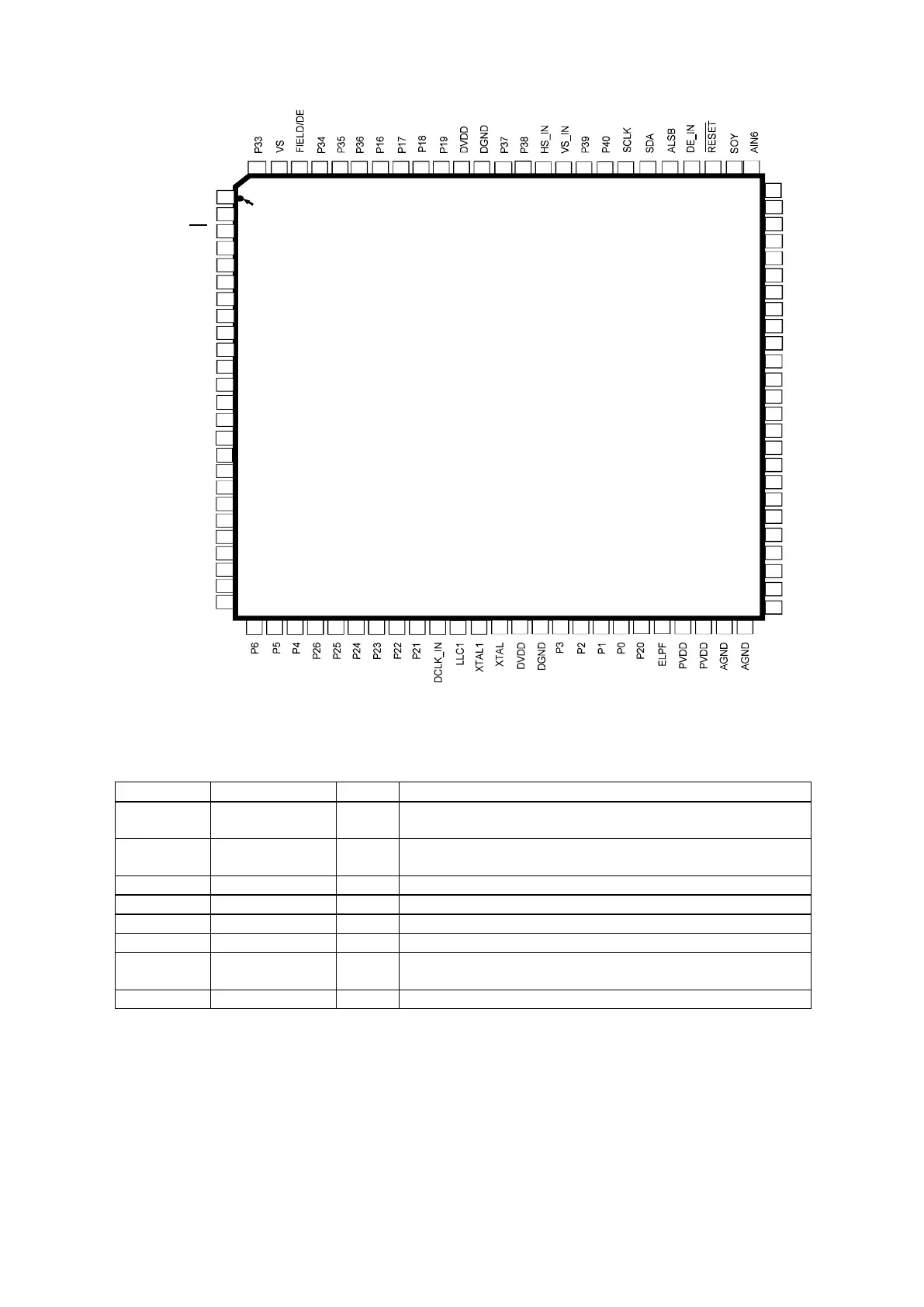
1.7 Pin Description
45
26 27 28 29 30 31 32 33 34 35 36 37 38 39 40 41 42 43 44
3
4
5
6
7
1
2
8
9
98 97 96
95 94
93 92
91 90
89 88 87 86 85 84 83 82 81
80
79 78 77
76
99
100
56 AIN2
AIN8
AIN1
AIN7
SOG
AIN9
AIN3
TEST1
AGND
CAPY1
CAPY2
AVDD
REFOUT
CML
AGND
BIAS
CAPC1
CAPC2
TEST0
AIN10
AIN4
AIN11
AIN5
AIN12
FB
57
58
59
60
61
62
63
64
65
66
67
68
69
70
71
72
73
74
75
55
54
53
52
51
ADV7403
20
P11
17
18
19
P32
P31
INT
CS/HS
DGND
DVDDIO
P15
P14
P13
P12
DGND
DVDD
P29
P28
SFL/SYNC_OUT
SCLK2
DGND
DVDDIO
SDA2
21
P10
22
P9
23
P8
24
P27
25
P7
46
47 48 49 50
LQFP
TOP VIEW
(Not to Scale)
Pin1
Identifier
10
11
12
13
14
15
16
Figure 2: Pin Configuration
Table 1: Pin Function Description
Pin No. Mnemonic Type Function
5, 11, 17,
40, 89
DGND G Digital ground
49, 50, 60,
66
AGND G Analog ground
6, 18 DVDDIO P Digital I/O supply voltage (3.3 V).
12, 39, 90 DVDD P Digital core supply voltage (1.8 V).
63 AVDD P Analog supply voltage (3.3 V).
47, 48 PVDD P PLL supply voltage (1.8 V).
51 FB I FB is a fast switch overlay input that switches between CVBS
and RGB analog signals.
54, 56, 58, AIN1–AIN12 I Analog video input channels.