4. SYSTEM ERROR
Check 1
• Indication of abnormalities with the EEP-ROM (DSP
PWB / IC15) Interface
This indicates a communication error wherein the ACK
will not return for 2 seconds or more while the system is
in communication with the EEP-ROM (DSP PWB / IC15).
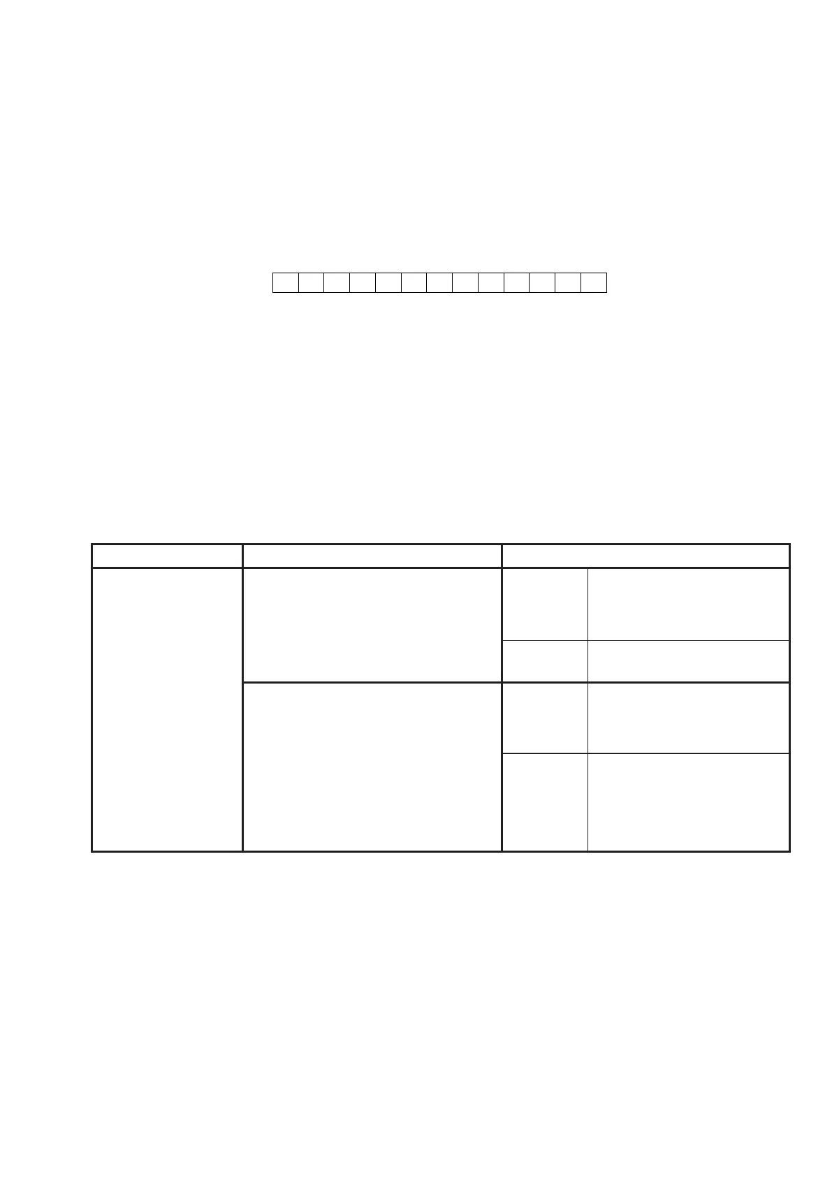
- Message on FL display
Points to be checked
1) The IIC Clock Line (IC17/116pin – IC15/6pin) is normal
when the power is ON;
2) The IIC Data Line (IC17/117pin – IC15 / 5pin) is normal
when the power is ON;
3) The IC15/8pin is supplied with VCC +3.3V;
4) If none of the above is negative, the IC15 may be
having a defect.
Check 2
4. SYSTEM ERROR
Check 1
• EEP-ROM (DSP PWB / IC15) Interface異常検出
EEP-ROM (DSP PWB / IC15)との通信でACKが帰って
こない状態(通信エラー)が約2秒以上生じた場合FL
Displayに下記の様な表示がされます。
- FL DisplayへのError表示
回路上の確認箇所
① Power ON時にIIC Clock Line (IC17/116pin - IC15 /
6pin)が正常なのを確認する。
② Power ON時にIIC Data Line (IC17/117pin - IC15 /
5pin)が正常なのを確認する。
③ IC15 / 8pinにVCC (+3.3V)が供給されていることを確
認する。
④ 上記の①−③に不具合が生じていない場合はIC15の不
良が考えられます。
Check 2
Error Detection Reason Check points
STANDBY LED
FLICKERING 500 msec.
NOTE : HOW TO
RECOVER FROM THIS
SYSTEM ERROR
The product can
recover from the
SYSTEM ERROR when
the user turns on and
then off the STANDBY.
However, once any
of the right errors is
redetected, the product
goes into STANDBY
again.
1. Detection of an abnormality on ±15V
Supply. (_P LINE FAIL)
CPU (IC17) 135pin _P LINE FAIL :
0 V ~ ± 15V Supply is fail)
5 V ~ ± 15V Supply is normality
Connection
REGURATOR PWB : CN66/3pin,
CPU PWB : BN66/3pin.
± 15V Supply
REGURATOR PWB : D901, R903/
R904, IC93/IC94 fail
2. +5VD supply Error Detection.
(_5V DOWN)
Main-CPU (IC17) 137pin _5V DOWN :
0 V ~ No +5VD (fail),
5 V ~ +5VD is work (normality)
Connection IC17/137pin + 5VD (RC53)
+5VD Supply
DSP PWB : CN80/6,7pin,
INPUT PWB : BN80/6,7pin
BN50/4,5pin
REGULATOR PWB : CN50/4,5pin
IC92, D902, F901 fail