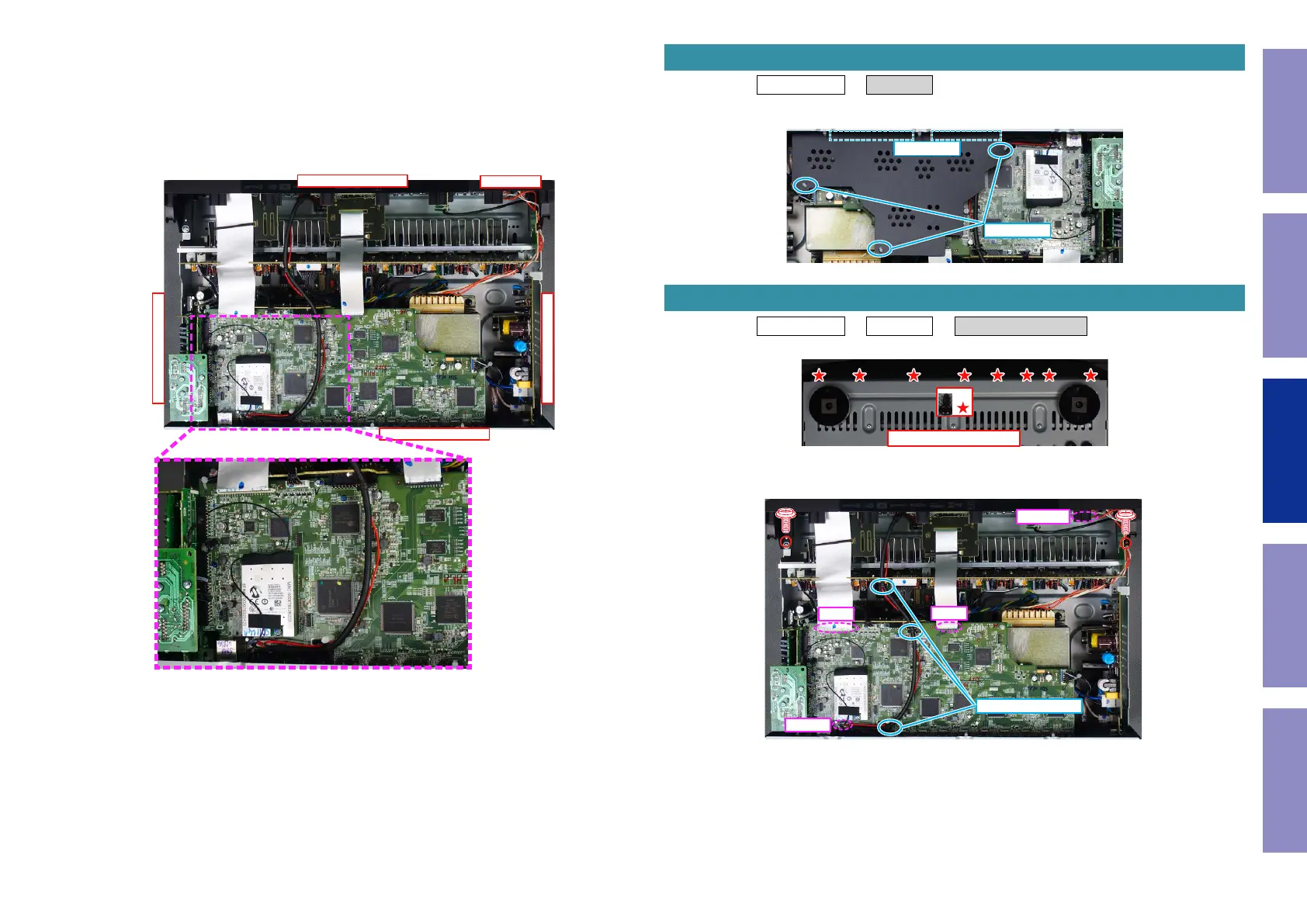
Explanatory Photos for DISASSEMBLY
• For the shooting direction of each photos used in this manual, see the photo below.
• A, B, C and D in the photo below indicate the shooting directions of photos.
• The photographs with no shooting direction indicated were taken from the top of the unit.
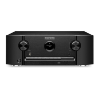
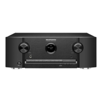
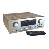
• Photos of SR5011 U are used in this manual.
The viewpoint of each photograph
(Shooting direction : X) [View from the top]
↑Shooting direction: A↑
↓Shooting direction: B↓
↓Shooting direction: D↓
↑Shooting direction: C↑
↑
Front side
↑
Proceeding : TOP COVER → COVER
(1) Remove the PCB HOLDER. Remove the TAPE.
Proceeding : TOP COVER → COVER → FRONT PANEL ASSY
(1) Remove the screws.
(2) Remove the screws. Remove the CORD HOLDER and connectors. Remove the FFC.
1. COVER
HOLDER
TAPE
2. FRONT PANEL ASSY
View from the bottom
x8
N1008
FFC
FFC
CP4400
CORD HOLDER
66
Caution in
servicing
Electrical Mechanical Repair Information Updating