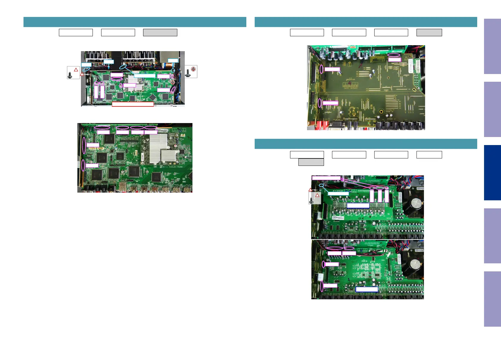
Proceeding : TOP COVER → REAR PANEL → DIGITAL PCB
(1) Removethescrews.RemovetheRivet.Cutthewireclamp,thenremovetheconnector.
RemovetheFFC.RemovetheSTYLEPIN.
(2) Removetheconnector.
4. DIGITAL PCB
↑Shooting direction: A↑
x1
x1
BN321
CN781
CN704
CN903
JK433
FFC
Rivet
STYLE PIN
CUT
CUT
BN24A BN26A BN25A BN21A
BN23A
BN27A
Proceeding : TOP COVER → REAR PANEL → DIGITAL PCB → VIDEO PCB
(1) Removetheconnector.
Proceeding : TOP COVER → REAR PANEL → DIGITAL PCB → VIDEO PCB
→ INPUT PCB
(1) Removethescrews.Removetheconnector.RemovetheSTYLEPIN.
5. VIDEO PCB
BN21B
BN27B
BN28B
6. INPUT PCB
x1
CN706
BN461
BN462
From AMP PCB
BN26CBN24C
BN64C
BN23C
HDAM PCB
STYLE PIN
INPUT PCB
Before Servicing
This Unit
Electrical Mechanical Repair Information Updating
83