S
ection
2
This LED blinks slowly when selecting single or three phase sensing via the front panel
push buttons. When in this adjustment mode, LED #1 is on if single phase sensing is
selected, LED #3 is on if three phase sensing is selected.
This LED blinks slowly when the “Coarse Voltage” level is selected for adjustment via the
front panel push buttons.
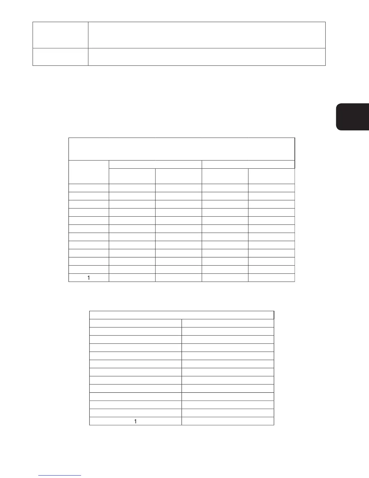
Indication of a setting level is provided by the 12 front panel LED indicators. The upper limit of a setting range is
represented by the top LED which is labeled GEN/LAG and MAX. The lower limit of a setting range is represented
by the bottom LED which is labeled MIN and ABSORB/LEAD. The setting range for each LED is summarized in
Tables 2-4 through 2-15. LEDs in the tables are numbered from 1 to 12 with 1 being the lowermost LED (labeled
MIN/ABSORB/LEAD) and 12 being the uppermost LED (labeled GEN /LAG/MAX.
Table 2-4. Coarse Voltage Adjust Setting Ranges
Coarse Voltage – LED 1 Blinking Slowly
Table 2-5. Sensing Mode (Single-phase/Three-phase) Select
Single-phase/Three-phase select – LED #2 Blinking Slowly