MOUNTING
ARRANGEMENTS
Excessive temperatures may affect
the
performance of the instrument. Completely
remove the plastic
cover,
if one is supplied over the case, and
avoid
standing
the instrument on
or
close to other equipment which
is
hot.
CONNECTING TO SUPPLY
Before connecting the instrument to the AC supply, check the setting of the voltage
selector switch
which
is an integral part of the supply connector
at
the
rear of the instrument.
Voltage selector
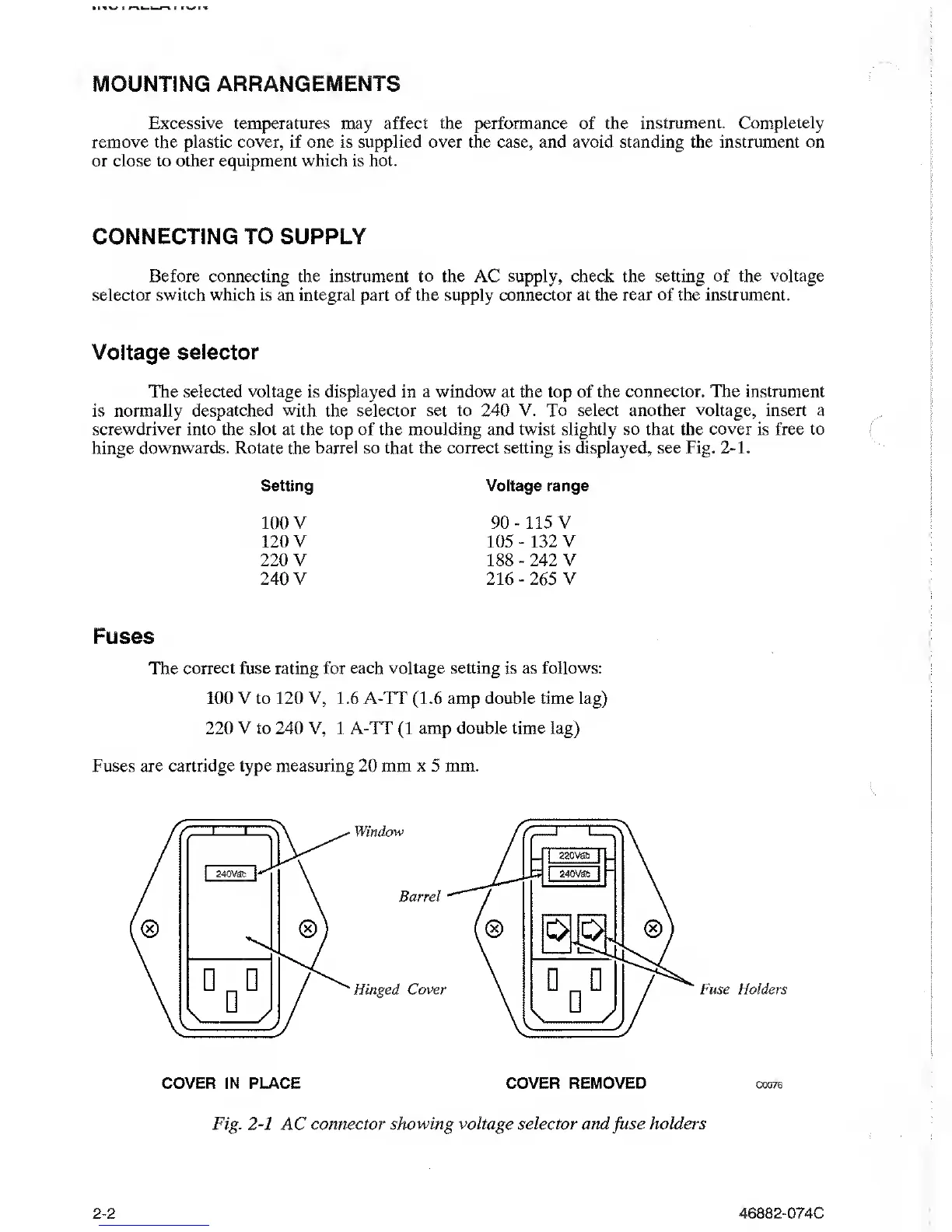
The selected voltage is displayed in a window at the top of the connector. The instrument
is normally
despatched with
the
selector set to 240 V. To select another voltage, insert a
screwdriver into the slot at the top of the moulding and twist slightly so that the
cover
is free
to
hinge
downwards.
Rotate the
barrel so that the correct setting is displayed, see Fig.
2-1.
Setting Voltage range
100
V
90-
115 V
120
V
105-
132 V
220
V
188
-
242 V
240 V
216
-
265
V
Fuses
The correct fuse rating for
each voltage
setting is as follows:
100
V
to 120
V,
1.6 A-TT
(1.6
amp
double time lag)
220 V to 240 V, 1 A-TT
(1
amp double time lag)
Fuses are cartridge type measuring 20
mm
x
5
mm.
Fig.
2-1
AC connector
showing voltage selector and
fuse
holders
2-2
46882-074C