*
1 1w
i
ru-iMfi * ivn
Supply cable
The AC supply cable is fitted
at one end with a socket
which
mates
with
the AC
connector on the rear
panel.
When
fitting a supply plug, ensure that connections are made
as
follows:
Earth
-
Green/Yellow
Neutral
-
Blue
Live
-
Brown
When attaching the supply
lead to a non-soldered plug, it is recommended that the tinned ends
of
the lead
are cut off to avoid intermittent connections resulting
from
cold flow.
GENERAL
PURPOSE INTERFACE BUS (GPIB)
The GPIB interface built
into the 2040 Series enables the signal generators to be remotely
controlled to form
part of an automatic measuring system.
GPIB cable connection
Connection
to other equipment which has a 24-way connector to IEEE Standard
488 is
made
using the rear panel GPIB socket. For this purpose,
the GPIB cable assembly, available as
an optional accessory,
(see Chap. 1 Accessories') may be used.
GPIB
connector contact assignments
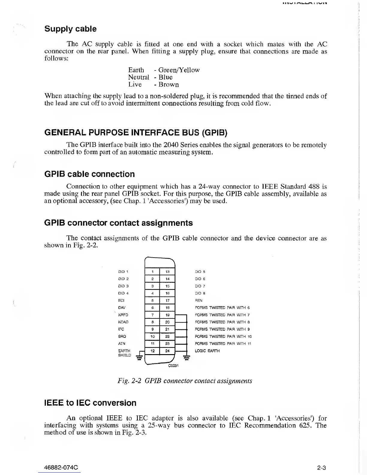
The contact assignments
of
the
GPIB cable connector and
the device
connector are as
shown
in
Fig.
2-2.
DIO 1
DIO 2
DIO
3
DIO
4
EOI
DAV
NRFD
NDAC
IFC
SRQ
ATN
EARTH
SHIELD
DIO 5
DIO 6
DIO 7
DIO 8
REN
FORMS TWISTED PAIR
WITH 6
FORMS TWSTED PAIR WITH 7
FORMS TWSTED PAIR WITH 8
FORMS TWSTED PAIR WITH 9
FORMS TWSTED PAIR WITH 10
FORMS TWSTED PAIR WITH 11
LOGIC EARTH
Fig.
2-2
GPIB connector contact assignments
IEEE to IEC conversion
An
optional
IEEE to IEC adapter is also available (see Chap.
1
Accessories’)
for
interfacing with systems using a
25
-way
bus
connector
to IEC Recommendation 625. The
method of use
is
shown
in Fig.
2-3.
46882-074C
2-3