Model ESM301 / ESM301L Test Stand User’s Guide
23
For non-relaxing materials such as metal springs, the oscillation should stop shortly after the holding force
is reached.
Note:
Preload and Load Holding cannot be enabled simultaneously.
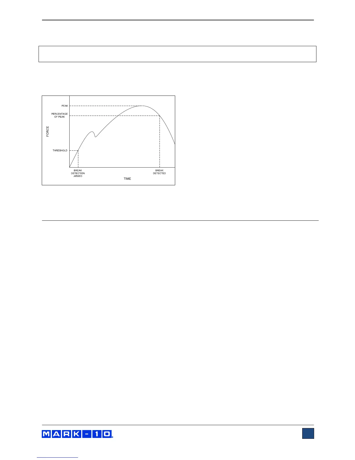
5.7 Break Detection Mode
In this mode, the crosshead will stop when a sample break has occurred. This action occurs when the
force has decreased to a specified percentage of peak, as illustrated below:
If enabled, an auto-return sequence or single-cycle sequence may follow break detection.
6 COMMUNICATION
6.1 Setup
The ESM301 can transmit force and travel (optional) data to a PC. The following settings are required for
proper functioning of all test stand functions and data output:
Force gauge / indicator (Series 5 / 7 only):
- RS-232 communication
- 9,600 baud rate
ESM301 test stand menu:
- CONTROL: CONSOLE (this menu is only shown if the PC Control function is installed; PC
Control is not required for data output)
- STOP & PAR (stop bits and parity): 8-1n (8 data bits, one stop bit, no parity)
Connection cables:
- Gauge / indicator to test stand: Part no. 09-1162
- Test stand to RS-232: Part no. 09-1056
- Optional RS-232 > USB converter: Part no. RSU100
If not using Mark-10 data collection software, ensure that the software’s communication settings match. A
number of data collection commands are available, highlighted in blue in the following section.