Model ESM301 / ESM301L Test Stand User’s Guide
4
2 SETUP AND SAFETY
2.1 Mounting
Place the stand on a clean, flat and level work area free from vibration. If desired, the stand can be
secured to the work area with 1/4-20 screws fastened into the underside of the base. Failure to properly
mount the test stand may make it more vulnerable to tipping, causing a hazardous situation.
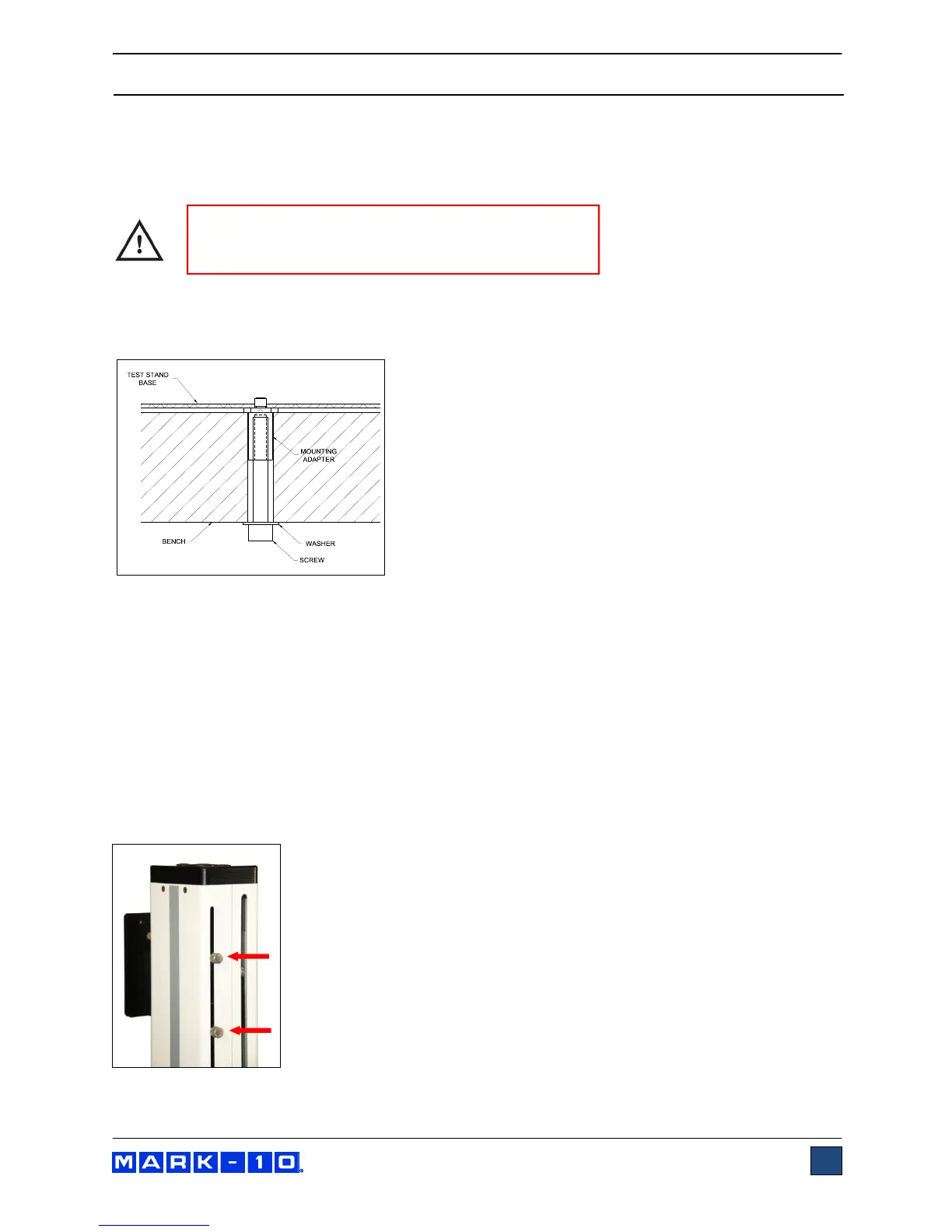
The test stand can also be mounted using the ESM301-003 mounting kit. Screws of various lengths are
supplied with this kit to accommodate a range of bench thicknesses. Refer to the illustration below for
proper assembly:
In general, the ESM301 can be mounted at any angle, although extra care should be taken during
installation and operation.
When the test stand is in a stable and secure position, install a force gauge with four thumb screws
(provided). Mark-10 gauges mount directly without adapters. Grips can be mounted onto the force gauge
and test stand base.
2.2 Installing the limit switches
Upper and lower limit switches are provided to stop crosshead travel at user-designated positions. Each
limit switch consists of an internal block riding along a rail, and an external thumbscrew. The
thumbscrews are shipped in a separate bag to avoid damage in transit. Refer to the illustration below for
proper installation:
IMPORTANT: Do not fasten any screws more than
0.25 in [6 mm] into the base of the test stand, or
damage to internal components can occur.