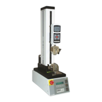
Model ESM301 / ESM301L Test Stand User’s Guide
5
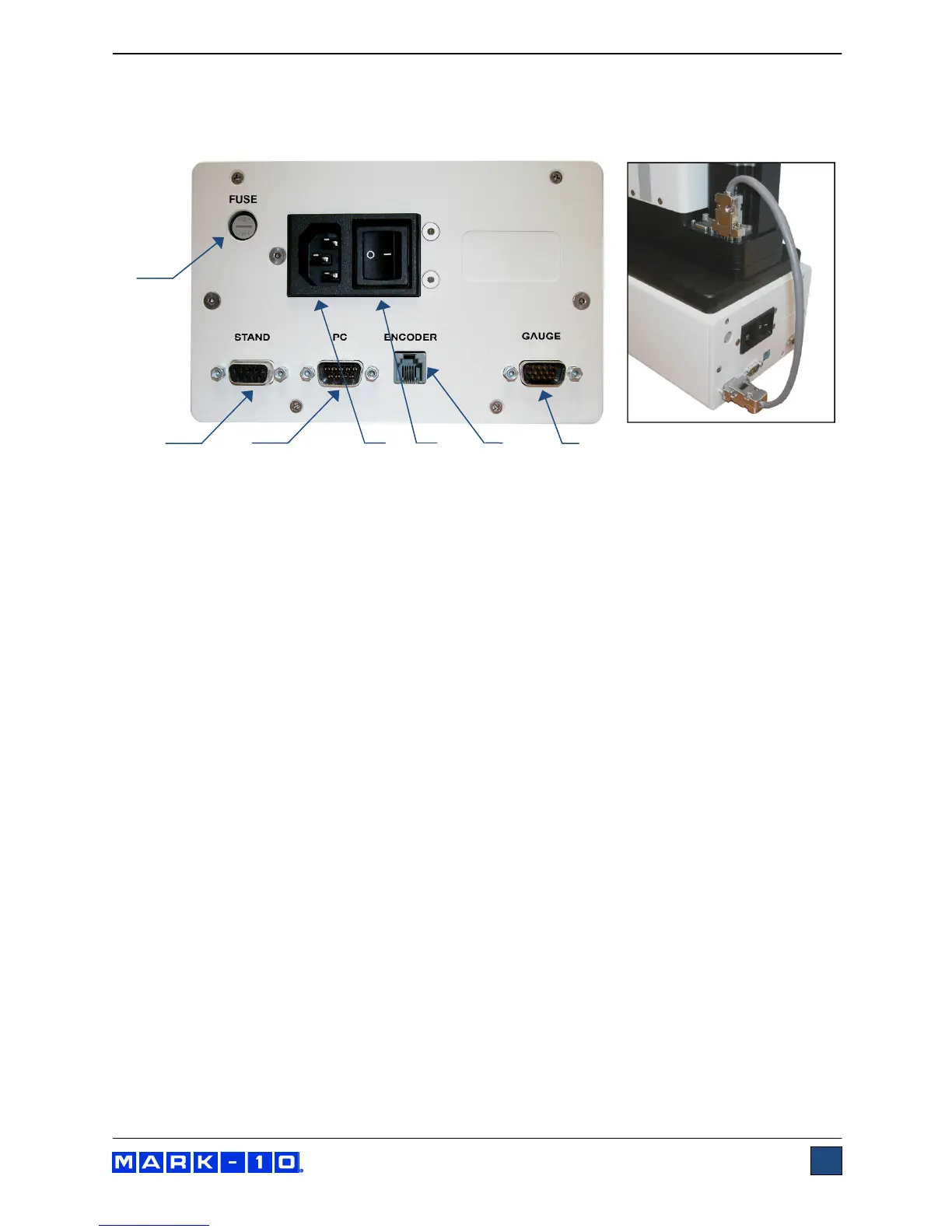
2.3 Connections and Outputs
The power plug and controller cable must be connected to the rear of the controller, as shown in the
illustration below:
1. Fuse
2. Controller Cable Connector
Plug one end of the cable into this connector, and the other end into the connector as shown in
the illustration on the right.
3. RS-232 Connector
Outputs force only or force and travel data via RS-232. Also allows for PC control, if appropriate
functions are enabled. Plug one end of the 09-1056 serial cable into this connector, and the other
end into a serial connector on a computer or USB converter.
4. Power Plug Receptacle
Plug the power cord in here. Refer to the Connecting Power sub-section for important safety
information.
5. Power switch.
6. Travel Indication Connector
Plug one end of the USB/RJ11 cable into this connector, and the other end into the mini USB
connector in the rear of the crosshead.
7. Force Gauge Cable Connector
Interfaces with a Series 7, 5 or 4 force gauge. Plug one end of the 09-1162 cable into this
connector, and the other end into the gauge.
2.4 Safety / proper usage
Typical materials able to be tested by the ESM301 include many manufactured items, such as springs,
electronic components, fasteners, caps, films, mechanical assemblies, and many others. Items that
should not be used with the ESM301 include potentially flammable substances or products, items that
can shatter in an unsafe manner, and any other components that can present an exceedingly hazardous
situation when acted upon by a force.
1
2
3
4
6
7
5