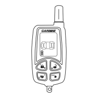
One Wire Multiplexing Door Locking Systems
Some vehicle’s (Chrysler, Mazda, Ford) use one wire to lock and unlock the doors. We have developed
patented plug-in fuse resistors to make the installation easier. Simply remove the fuses from ALA-DL1
module and replace them with the correct resistor value fuses that match the vehicles door lock signal
requirements.
ALA-DL1 Wiring:
1. Connect both the green (lock) and the blue (unlock) wires to the vehicles one wire lock/unlock wire.
2. Connect our violet polarity input wire to +12v or to ground. To match vehicle’s door lock polarity.
3. The white and the brown wires will not be used.
Blue Wire
Violet Wire To B+ or Ground as Required
White Wire No Connection
Brown Wire No Connection
Lock Fuse 1
Unlock Fuse 2
Black 3-Pin
Housing
Green Wire
ALA-DL1
To Vehicles
Lock/Unlock Wire
Note: Orange Wire from ALA-DL1 must be connected to +12V
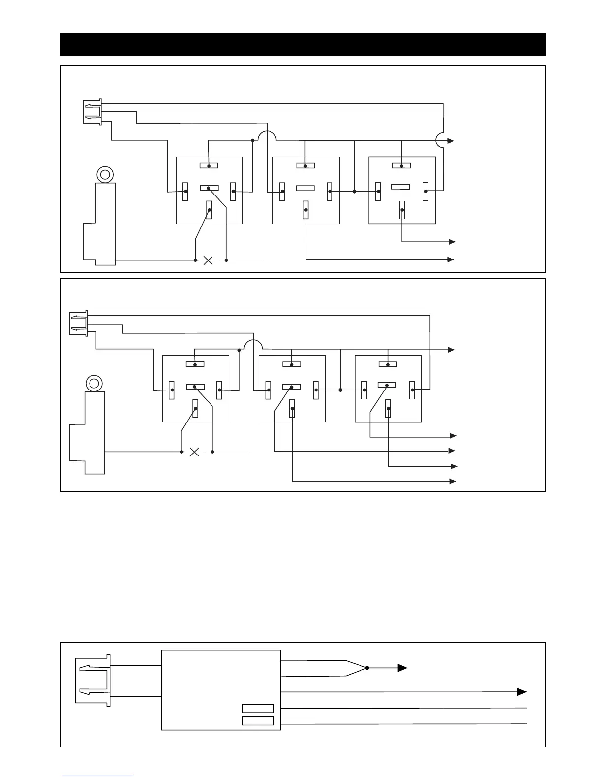
Step 4: Optional Accessory Connections (continued)
87
87A
85
86
30
87
87A
85
86
30
Orange Wire
Red Wire
To +12 Volts
(Battery +)
To Power
Door Lock
Switch
Lock/Unlock
Wires
Lock
Unlock
87
87A
85
86
30
Black Wire
+ Unlock
Cut
Driver's
Door
Motor
7
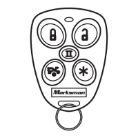
Unlock Driver's Door First Wiring for 5-Wire Ground at Rest Door Locking Systems
87
87A
85
86
30
87
87A
85
86
30
Orange Wire
Red Wire
To +12 Volts
(Battery +)
To Power
Lock Switch
To Power
Lock Motors
Lock
Lock
Unlock
Unlock
87
87A
85
86
30
Black Wire
+ Unlock
Cut
Driver's
Door
Motor
M5A-IM 9/10/04 9:27 AM Page 7